
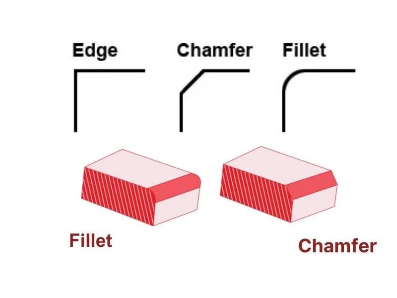
A shaft shoulder cracks at 60,000 cycles because the designer specified a chamfer where a fillet was needed — the stress concentration factor at that sharp transition was 2.5× higher than it would have been with a proper radius. On the flip side, a housing pocket takes 40% longer to machine because every internal corner calls for R1 fillets that force the use of 2 mm end mills running at half the feed rate of standard tooling. We deal with both scenarios regularly. The fillet vs chamfer decision isn’t cosmetic — it directly drives fatigue life, machining cost, and assembly behavior on every CNC part we produce.
This article compares fillets and chamfers from three integrated perspectives: engineering design intent, stress behavior, and CNC manufacturability. We cover geometry definitions, key differences, stress concentration effects, radius and chamfer sizing guidelines, machining cost and tooling implications, drawing standards, and industry-specific use cases. Whether you’re a designer specifying edge features, an engineer reviewing fatigue life, or a buyer evaluating part cost, the goal is to make fillet vs chamfer a deliberate engineering choice — not a default.
What Are Fillets and Chamfers?
Fillet
A fillet is a rounded transition defined by a radius (e.g., R2, R5) connecting two intersecting surfaces. Internal fillets appear at pocket bases, slots, and shoulders. External fillets smooth outside edges and profile transitions. The primary engineering purpose: creating a smooth, continuous transition that reduces abrupt geometry changes and lowers stress concentration under load. Internal fillets are especially critical in load-bearing parts where sharp corners become crack initiation sites.
Chamfer
A chamfer is a flat, angled edge — typically specified as distance × angle (e.g., 1 × 45° or C1). The most common specification is 45° because it aligns with standard cutting tools and simplifies programming. Chamfers remove sharp edges, reduce burrs, and provide lead-in geometry for assembly (shafts into bores, fasteners into threads). They’re faster and easier to produce than fillets.
Key distinction from bevels: Chamfers are functional edge treatments specified in dimensional design. Bevels are typically associated with weld preparation. Different intent, similar geometry.
Key Differences: Fillet vs Chamfer
| Dimension | Fillet | Chamfer |
|---|---|---|
| Geometry | Curved radius transition | Flat angled transition |
| Stress behavior | Smooth load flow, lower peak stress | Higher localized stress than fillet |
| Machining | Tool-radius dependent, may need extra passes | Simple, standard tools, single pass |
| Cost and cycle time | Higher (especially internal fillets) | Lower, shorter machining time |
| Assembly | Safe edges, less insertion guidance | Excellent lead-in for assembly |
The fundamental trade-off: fillets manage stress and fatigue, chamfers manage manufacturability and assembly. Effective design uses both — fillets where loads demand it, chamfers where cost and function allow it.
How Fillets and Chamfers Affect Stress
Why Sharp Corners Fail
A sharp 90° corner interrupts the natural load path, forcing stress to “turn abruptly.” This creates a stress concentration factor (Kt) that amplifies local stress well above the nominal average. Even when overall stresses look safe, high Kt at corners drives fatigue crack initiation under cyclic loading. That’s why failures overwhelmingly start at internal corners, shoulder transitions, and keyway roots — not in uniform sections.
Why Fillets Reduce Stress
A fillet restores curvature continuity between surfaces. The smooth radius lets load flow gradually, reducing peak stress gradients. Larger radii lower the concentration factor further, though benefits diminish beyond a certain size. Based on our production data, increasing a shaft shoulder fillet from R0.5 to R2 on 4140 steel typically reduces the stress concentration factor from ~2.5 to ~1.5 — roughly doubling expected fatigue life under equivalent cyclic loading.
When Chamfers Are Acceptable
Chamfers don’t redistribute stress as effectively as fillets, but they’re structurally acceptable in several scenarios: low-load or static applications where stresses stay well below fatigue thresholds, non-critical regions (external edges, cosmetic features, handling surfaces), and designs where assembly guidance matters more than stress — press fits, bearing insertion, fastener lead-ins.
Design rule: Use fillets to manage stress and fatigue. Use chamfers to manage assembly, safety, and manufacturing cost. Don’t treat them as interchangeable.
Sizing Guidelines
Fillet Radius Selection
Radius should scale with part size and loading level — not be chosen arbitrarily. In CNC machining, internal fillet size directly depends on cutting tool radius. Specifying a radius smaller than standard tool sizes forces small-diameter cutters, increasing cycle time, deflection risk, and cost.
One common pitfall we see: designers specifying R0.5 internal fillets throughout a part when R1.5 or R2 would provide equivalent stress relief with 30–40% shorter machining time. Specify internal fillets slightly larger than the stress-minimum to allow standard tooling. Over-sizing carries its own risks — excessively large radii can reduce bearing length, weaken thin walls, or interfere with assembly fits.
Chamfer Sizing
The 45° default aligns with standard tools and simplifies programming. Chamfer length should match functional need: short chamfers for edge breaking and safety, longer chamfers for guiding shafts, pins, or fasteners into mating features. Oversized chamfers can reduce effective engagement length. Undersized chamfers may fail to prevent burrs or assembly damage.
CNC Machining: Cost, Tooling, and Accuracy
Machining Fillets
Internal fillets require end mills or corner-radius tools matching the specified radius. Smaller tools mean slower feeds, higher deflection risk, and more passes for surface quality. In deep pockets or narrow slots, tool access further limits achievable radii. From a machining standpoint, fillets almost always cost more than chamfers — the question is whether the stress reduction justifies that cost.
In our shop floor experience, unnecessary R0.5 internal fillets across a complex aluminum housing added 35% to cycle time compared to R2 fillets that provided equivalent structural performance. That’s a direct cost penalty for over-specification.
Machining Chamfers
Standard chamfer tools cut edges quickly in a single pass with minimal toolpath complexity. Chamfer tooling is more robust, less sensitive to wear, and easier to inspect. For repeatable CNC production, chamfers deliver lower cycle time, fewer tool changes, and more predictable cost.
Cost and Quality Summary
Chamfers almost always outperform fillets on cycle time and cost. Internal fillet radii are indirectly defined by tool geometry, so accuracy depends heavily on tool condition. Residual internal corner radii — unavoidable in CNC — must be accounted for during design to prevent fit or stress issues. Chamfers are easier to measure, repeat, and tolerate minor variation without functional impact.
Drawing Standards
Dimensioning Fillets
Use R notation (R2, R5). Avoid over-dimensioning identical fillets at every corner — use a general note (“ALL INTERNAL FILLETS R3 U.O.S.”) to reduce clutter per ISO 129 or ASME Y14.5 conventions. Conflicting fillet callouts create CNC programming ambiguity.
Dimensioning Chamfers
Use distance × angle (1 × 45°) or C1 notation. Avoid double-dimensioning (specifying both linear distance and resulting face length), which overconstrains the geometry. A single unambiguous definition lets the CNC programmer select the most efficient toolpath.
General Practice
Consistency across drawings — same conventions for fillets and chamfers — reduces interpretation risk, speeds programming, and minimizes rework. Both ISO and ASME standards emphasize communicating functional intent, not prescribing process detail.
Industry Applications
Automotive and power transmission: Fillets dominate load-bearing regions — shaft shoulders, gear hubs, splines — where fatigue life under cyclic torque and bending governs design. Chamfers handle assembly lead-ins for bearing insertion and spline engagement.
Industrial equipment: Balance shifts toward manufacturability. Frames, brackets, housings, and enclosures often use chamfers for edge safety, deburring efficiency, and batch consistency. Fillets appear selectively at high-load junctions or welded interfaces.
Medical and precision devices: Fillets in precision load paths for fatigue resistance. Chamfers on external edges for handling safety and cleanability. Tight tolerances and predictable CNC outcomes are mandatory — making clear fillet-vs-chamfer intent essential during design.
Conclusion
Fillet vs chamfer is an engineering decision that directly affects stress behavior, fatigue life, machining cost, and assembly performance. Fillets manage stress concentration through smooth curvature — essential in load-bearing, cyclically loaded regions. Chamfers manage manufacturability, assembly guidance, and handling safety — ideal for non-critical edges and cost-sensitive features. The best designs use both deliberately, matching each feature to its functional purpose.
Decisions made at the CAD stage set the boundary conditions for CNC cost, tolerance capability, and long-term reliability. Aligning fillet and chamfer choices with true engineering intent produces more predictable quality, lower total cost, and fewer downstream issues. Need help optimizing edge features for your CNC-machined parts? [Contact our engineering team] for DFM review and precision manufacturing support.
FAQ
Is a fillet always stronger than a chamfer?
In fatigue-critical regions, yes — fillets lower stress concentration more effectively. However, for lightly loaded, static, or non-critical features, the structural advantage may be negligible. A chamfer can be sufficient without compromising performance in those cases.
Does a larger fillet always reduce stress?
Up to a point. Increasing radius lowers the stress concentration factor, but benefits diminish beyond a certain size. Excessively large fillets can reduce functional length, interfere with mating parts, or increase machining cost. Balance stress relief with geometric and manufacturing constraints.
Why do CNC machinists prefer chamfers?
Chamfers are faster, simpler, and more predictable. They cut in a single pass with standard tools and are less sensitive to wear. Internal fillets require smaller cutters, longer cycle time, and tighter process control. When stress reduction isn’t critical, chamfers save time and money.
How do fillets affect machining cost?
Internal fillets can significantly increase cost. Small radii force small tools with slower feeds and more passes. Tool accessibility in deep pockets further extends cycle time. Unnecessarily small fillet radii are one of the most common drivers of avoidable CNC cost in custom parts.
Can fillets and chamfers be combined in one part?
Yes — and in most well-designed components, they should be. Fillets at load-bearing transitions manage stress and fatigue. Chamfers on external edges and assembly interfaces handle safety and insertion guidance. Combining both optimizes structural performance and manufacturability simultaneously.


