
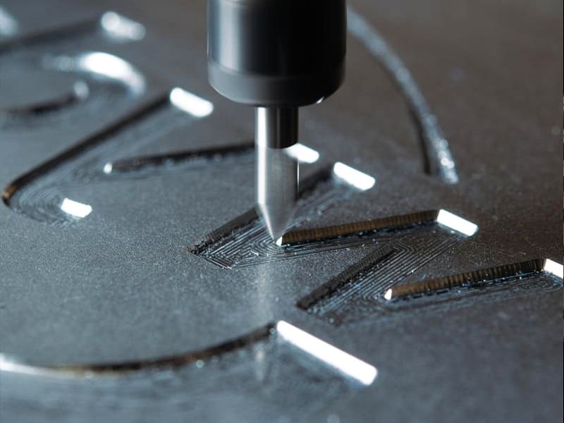
Quick Answer: CNC engraving is a subtractive machining process in which a rotating cutting tool physically removes material to create permanent markings — serial numbers, logos, QR codes, and functional patterns — at depths of 0.02–2 mm. Unlike laser marking, which alters the surface through heat to shallow depths of 0.005–0.05 mm, CNC engraving produces mechanically permanent grooves that survive coating, abrasion, chemical cleaning, and long-term wear. It is the correct method for aerospace traceability, medical device UDI marking, industrial nameplates, and any application requiring markings that remain readable after surface treatment or extended service exposure.
What Is CNC Engraving?
CNC engraving is a subtractive manufacturing process in which a rotating cutting tool — typically a V-bit, end mill, or dedicated engraving cutter — removes material from a workpiece surface along computer-controlled toolpaths to create precise, permanent geometric features. The process is governed by G-code generated from a CAD/CAM workflow, ensuring high positional accuracy (±0.01–0.05 mm typical) and complete repeatability across production batches.
The defining characteristic of CNC engraving is physical depth. The tool cuts into the material, creating a recessed groove that exists as a three-dimensional feature rather than a surface-level color change or coating. This depth is what gives CNC engraving its durability: a 0.3 mm deep engraved serial number on a stainless steel aerospace component remains fully readable after anodizing, painting, shot blasting, chemical cleaning, and years of abrasion that would obliterate any surface-applied marking.
For engineers and OEM procurement teams specifying part marking, the choice between CNC engraving, laser marking, and other methods is fundamentally a durability and compliance question. When marking must survive the component’s operational lifetime — and particularly when it must survive intermediate manufacturing operations like coating and heat treatment — CNC engraving is the answer.
How CNC Engraving Works: The Engineering Workflow
CNC engraving follows a structured digital-to-physical workflow where errors introduced at any stage propagate to finished marking quality.
Stage 1: CAD Design
The engraving content — text, logos, symbols, part numbers, 2D data matrix codes — is defined as vector geometry in CAD software. Critical design decisions at this stage include:
Minimum feature size: The smallest engraving feature must be achievable with available tooling. A 0.1 mm diameter V-bit tip can produce 0.1 mm wide lines; attempting to engrave a 0.05 mm line with this tool produces a blurred or inconsistent result. As a general guideline, minimum line width should be at least equal to the tool tip diameter.
Font selection: For text engraving, single-line (stroke) fonts are significantly more efficient and produce cleaner results than filled or outline fonts. Stroke fonts define text as a single centerline path that the cutter follows directly; outline fonts require tracing a closed perimeter and potentially filling the interior, multiplying machining time for the same visual outcome.
Character size: Minimum practical text height for CNC engraving is approximately 1.5–2 mm for standard tools. Below this height, character spacing becomes too tight for tool access and stroke legibility suffers.
Stage 2: CAM Toolpath Generation
CAM software converts CAD geometry into machine instructions, defining the cutting strategy:
Depth approach: Constant-depth toolpaths program the tool to cut uniformly to a specified Z depth — appropriate for text and serial numbers where consistent depth across all characters is required for readability. Variable-depth (V-carving) varies depth based on local feature width, producing naturally tapered grooves that give logos and decorative engravings a refined three-dimensional appearance.
Tool and parameter selection: V-bit included angle affects line width at a given depth — a 60° V-bit at 0.1 mm depth produces a narrower groove than a 90° V-bit at the same depth. Feed rate and spindle speed are material-specific: aluminum accepts high speeds (18,000–24,000 RPM, 500–1,500 mm/min feed); stainless steel requires significantly lower values (8,000–12,000 RPM, 100–300 mm/min) to manage heat generation and tool wear.
Stage 3: CNC Execution
The machine executes the programmed toolpath under CNC system control. Machine rigidity, spindle runout, and workholding stability directly affect engraved quality. Vibration during engraving — from poorly balanced spindles, excessive tool overhang, or inadequate workholding — manifests as wavy lines, inconsistent groove width, and variable depth visible in the finished marking.
Accuracy and Error Sources
| Factor | Effect on Engraving Quality | Control Method |
|---|---|---|
| Tool condition | Line sharpness, depth consistency | Scheduled tool replacement |
| Machine rigidity | Positional accuracy, smooth lines | Rigid CNC, minimize tool overhang |
| Workholding stability | Alignment, no movement during cut | Vacuum or mechanical clamping |
| Material properties | Chip formation, surface finish | Material-matched parameters |
| Tool runout | Line width variation | Precision collet or shrink-fit holder |
| Surface flatness | Depth consistency across feature | Flat reference surface or probe compensation |
CNC Engraving Depth: Selecting by Application
Depth is the parameter that determines how long an engraving remains functional under the specific conditions the component will experience. Specifying depth based on service environment is more reliable than selecting from generic “shallow” or “deep” categories.
Depth Reference by Application Type
| Application | Recommended Depth | Rationale |
|---|---|---|
| Fine decorative marking | 0.02–0.05 mm | Aesthetic only, minimal wear exposure |
| Standard text/logo, indoor | 0.05–0.1 mm | Office or light-duty indoor equipment |
| Industrial part marking | 0.1–0.3 mm | Survives moderate handling and cleaning |
| Post-coating readable | 0.2–0.5 mm | Must remain legible after anodizing, painting |
| Harsh environment (outdoor, marine) | 0.3–1.0 mm | Long-term wear, abrasion, UV, chemicals |
| Deep industrial / tooling | 0.5–2.0 mm | Mold cavities, scale lines, alignment features |
The critical post-treatment depth threshold: for markings that must survive anodizing, powder coating, or plating, a minimum depth of 0.2–0.3 mm is generally required. Anodizing typically adds 0.01–0.025 mm of oxide layer; powder coating 0.05–0.12 mm. A 0.05 mm deep engraving may be partially or completely filled by a powder coat layer, making the marking illegible.
Depth vs Performance Trade-Off
| Factor | Shallow (0.02–0.1 mm) | Deep (0.3–2 mm) |
|---|---|---|
| Appearance quality | High precision, clean edges | Wider grooves, visible tool marks at higher magnification |
| Durability | Moderate | Very high |
| Post-coating readability | Poor | Good to excellent |
| Machining time | Short | Longer |
| Tool wear | Low | Higher (especially in hard materials) |
| Risk on thin parts | Low | Deformation risk on walls < 3 mm thick |
For industrial components where markings must survive the product’s operational life, 0.1–0.3 mm is the standard working range. Depth below 0.1 mm is adequate only for markings that will never be coated and experience minimal abrasion.
Types of CNC Engraving and Marking Methods
Rotary CNC Engraving (Mechanical Cutting)
The standard CNC engraving process — a rotating carbide cutting tool removes material along programmed toolpaths. The dominant method for permanent industrial marking, with adjustable depth from 0.02 mm to 2 mm or more, compatibility with metals and plastics, and the highest durability of any marking method.
Tool types in common use:
- V-bits (30°, 60°, 90° included angle): Standard for text and logo engraving. V-geometry produces clean chip clearance and self-sharpening cutting behavior.
- Pointed engraving tools (tapered micro end mills): For fine detail requiring consistent groove width regardless of depth.
- Square end mills (0.2–1 mm diameter): For wider, flat-bottomed grooves and recessed areas requiring uniform floor finish.
Laser Engraving and Marking (Non-Contact Thermal)
Laser systems vaporize or discolor material through focused thermal energy without mechanical contact. Processing speed is significantly faster than rotary CNC engraving — fiber laser systems can mark a serial number on metal in under 1 second. However, feature depth is in the micron range (typically 0.005–0.05 mm), providing limited wear resistance and no post-coating readability.
Engineering limitation: Laser-marked features are surface-level modifications. After anodizing, painting, or significant abrasion, laser markings become partially or completely obscured. For traceability applications where markings must survive manufacturing processing and service, laser marking is appropriate only for components that will not be coated and experience minimal mechanical wear.
Diamond Drag Engraving (Scribing)
A diamond-tipped tool pressed against the workpiece surface scratches or plastically deforms a groove without cutting — no material removal. Produces very fine, precise lines with minimal depth (0.005–0.02 mm). Best for metal identification tags, jewelry engraving, and applications requiring ultra-fine lines on surfaces that cannot tolerate cutting forces.
Marking Method Comparison
| Method | Depth | Durability | Speed | Best Application |
|---|---|---|---|---|
| Rotary CNC engraving | 0.02–2 mm | Very high | Medium | Industrial, aerospace, post-coating marking |
| Laser marking | 0.005–0.05 mm | Medium | Very fast | High-volume, QR codes, uncoated cosmetic |
| Diamond drag | 0.005–0.02 mm | Low–medium | Slow | Fine labels, jewelry, delicate surfaces |
| Chemical etching | 0.01–0.2 mm | Medium–high | Medium | Thin sheet, complex 2D patterns, PCB |
CNC Engraving vs Laser Marking: Engineering Decision Guide
The choice between CNC engraving and laser marking is determined almost entirely by durability requirements.
When CNC Engraving Is the Correct Choice
Post-coating readability is required. If the part will be anodized, painted, powder-coated, or plated after marking, only CNC-engraved features deep enough to project above the coating layer will be legible afterward. This is a hard technical constraint that laser marking cannot overcome.
Parts experience wear, abrasion, or chemical cleaning. Aerospace components, industrial tooling, outdoor equipment, and marine hardware all experience surface conditions that progressively remove surface-level markings. CNC-engraved grooves maintain legibility because their physical geometry is preserved even as the surrounding surface wears.
Regulatory compliance requires permanent marking. FDA UDI requirements for medical devices, AS9100 aerospace traceability requirements, and ISO 9001 part identification requirements typically specify that markings must remain legible throughout the product’s intended service life. CNC engraving meets this requirement more reliably than laser marking for components processed or operated in conditions that degrade surface features.
When Laser Marking Is the Correct Choice
High production volume with minimal durability requirement. Laser marking a serial number on consumer electronics takes under 1 second; equivalent CNC engraving takes 30–90 seconds. For millions of units where cosmetic marking durability is adequate, laser’s throughput advantage is decisive.
Fine detail at micro scale. 2D data matrix codes, barcodes, and micro-text below approximately 1 mm character height are more reliably produced by laser than rotary CNC engraving, because laser spot size (0.02–0.05 mm) is smaller than achievable CNC tool tip diameter for production work.
Substrate cannot accept cutting forces. Thin foils, fragile electronic components, and delicate assemblies may be damaged by rotary CNC contact. Laser’s non-contact mechanism eliminates this risk.
Materials for CNC Engraving
Aluminum (6061, 7075, 5052)
The easiest metal to CNC engrave. Low hardness (60–150 HB), excellent chip formation, and high thermal conductivity produce clean, sharp-edged grooves with minimal tool wear. High cutting speeds are achievable, making aluminum engraving fast and cost-effective.
Anodized aluminum is a particularly effective combination — engraving through the anodize layer exposes bright base metal against the darker anodized surface, creating high visual contrast without paint fill. Post-anodize engraving of serial numbers and part codes is standard practice in aerospace and industrial component manufacturing.
Stainless Steel (304, 316, 316L)
Stainless steel engraving is achievable but parameter-sensitive. The material’s work-hardening tendency means cutting speeds must remain low enough to prevent hardening of the machined surface during cutting. Once work-hardened, subsequent tool passes face a significantly harder surface that accelerates wear. Coated carbide tools (TiAlN or AlCrN) are required; tool life monitoring is essential.
Standard parameters: 8,000–12,000 RPM spindle, 100–300 mm/min feed, flood coolant or high-pressure air blast for heat management.
Titanium (Ti-6Al-4V)
Technically feasible but expensive relative to aluminum or stainless. Low thermal conductivity requires very conservative parameters (30–50 m/min cutting speed, peck-style depth increments, high-pressure coolant). For aerospace titanium components where engraved part numbers are required, the process is well-established — but cycle time per part is substantially longer than equivalent aluminum work.
Plastics (ABS, Acrylic, PEEK, POM)
Engineering plastics engrave cleanly when parameters prevent heat buildup. The primary risk is melting rather than cutting if cutting speed is too low relative to feed rate — frictional heat softens material around the tool, producing smeared edges. Sharp tools, high spindle speed, fast feed rates, and air blast to clear chips and heat are the correct approach.
Material Engraving Comparison
| Material | Difficulty | Typical Spindle Speed | Key Challenge | Tool Recommendation |
|---|---|---|---|---|
| Aluminum 6061 | Easy | 18,000–24,000 RPM | Built-up edge prevention | Sharp carbide, DLC coating |
| Brass | Easy | 15,000–20,000 RPM | Built-up edge at high temperature | Sharp carbide |
| ABS / Acrylic | Easy | 12,000–18,000 RPM | Heat / melting | Sharp tools, air blast |
| Stainless 316L | Medium–Hard | 8,000–12,000 RPM | Work hardening, tool wear | Coated carbide (TiAlN) |
| Titanium Ti-6Al-4V | Hard | 5,000–10,000 RPM | Heat concentration | Coated carbide, high-pressure coolant |
Applications of CNC Engraving
Industrial Nameplates and Equipment Labels
Industrial equipment labels, control panel overlays, and safety nameplates require markings that survive oil, solvents, UV exposure, and periodic cleaning over 10–20-year service lives. CNC-engraved aluminum or stainless steel nameplates meet this requirement — the physical groove depth is unaffected by chemical exposure, coating, or moderate abrasion.
For nameplates with color fill (paint in engraved grooves for contrast), CNC engraving depth of 0.2–0.5 mm provides adequate groove volume for paint retention while the surrounding surface accepts anodizing or other finishing.
Aerospace Traceability
Aerospace component traceability requirements (AS9100 and customer-specific quality plans) mandate permanent part marking with part number, serial number, lot code, and manufacturer identification that must remain legible throughout the component’s service life — potentially spanning decades of thermal cycling, chemical cleaning, and mechanical load.
CNC engraving depth of 0.2–0.5 mm on titanium and aluminum aerospace structural components meets this requirement. The marking survives anodizing, chromate conversion coating, and primer application applied after machining. Laser marking at equivalent character size would be obliterated by these post-machining surface treatments.
Medical Device UDI Compliance
FDA 21 CFR Part 801 requires Unique Device Identification (UDI) marking on medical devices. For implantable and reusable surgical instruments that will be autoclaved, chemically sterilized, and handled extensively in clinical environments, markings must remain legible throughout the device’s service life. CNC-engraved UDI data matrix codes and text on stainless steel or titanium surgical instruments meet this requirement.
Marking depth must be sufficient for groove readability after repeated sterilization cycles (autoclave, gamma irradiation, chemical disinfectant exposure), while shallow enough that the groove does not create surfaces that trap biological material — typically 0.05–0.15 mm for sterile instrument applications.
Injection Molds and Tooling
CNC-engraved cavity numbers, date codes, and gate identification inside injection mold cavities provide production tracking throughout the mold’s operational life. Depths of 0.3–1.0 mm in hardened tool steel (H13, D2, P20) provide reliable long-term legibility through thousands of injection cycles.
Design Guidelines for CNC Engraving (DFM)
Minimum Feature Size
The minimum engraving line width is constrained by tool geometry — the cutting tip diameter sets the floor. Design features must be verified against the tooling capabilities specified for the job.
Practical minimums for reliable production:
- Standard industrial engraving: 0.3 mm minimum line width, 2 mm minimum character height
- Fine detail work with dedicated micro tooling: 0.1 mm line width, 1 mm character height
- Conservative production threshold for machine readability: 0.5 mm minimum character height
Font and Geometry Selection
Single-line (stroke) fonts are dramatically more efficient to engrave than outline or filled fonts — they require a single tool pass rather than a perimeter outline plus fill. For industrial marking where readability and efficiency are the priorities, stroke fonts are the correct default.
Italic, script, and decorative typefaces create difficult toolpath geometry and poor readability at typical industrial marking character sizes. Simple sans-serif fonts (Arial, Helvetica equivalents) produce the most reliable engraving results.
DFM Checklist for CNC Engraving
| Design Decision | Recommendation |
|---|---|
| Minimum character height | ≥ 2 mm for standard tools; ≥ 1.5 mm for fine tools |
| Minimum line width | ≥ 2× tool tip diameter |
| Depth specification | Derive from worst-case service condition |
| Font type | Single-line (stroke) fonts for efficiency; simple sans-serif for readability |
| Character spacing | Minimum 0.3 mm gap between adjacent strokes |
| Post-coating depth adjustment | Add 0.1–0.2 mm to depth if part will be coated |
| Thin part risk | Avoid depth > 0.5 mm on features with wall thickness < 3 mm |
| Engraving placement | Specify location relative to functional datums for position accuracy |
Cost Factors in CNC Engraving
CNC engraving is generally a low-cost addition to a machined part when performed in the same setup — the engraving operation runs after machining without refixturing, eliminating separate handling and setup cost. The cost structure depends on:
Material hardness is the dominant variable. Aluminum engraving is fast (0.5–2 minutes for a typical serial number), low tool wear, and low cost. Stainless steel engraving takes 2–5× longer due to reduced cutting speeds, with proportionally higher tooling consumption. Titanium is the most expensive metal option.
Depth and complexity multiply cycle time directly. Each 0.1 mm of additional depth adds machining time, particularly in multiple-pass operations. Complex logos with fine detail require slower feeds and more careful toolpath management than simple serial number text.
Batch size amortizes setup cost. The first-article programming and validation is non-recurring; subsequent batches cost only machining time and tooling. Per-unit engraving cost falls substantially as batch size increases.
Practical cost context: A simple serial number (10 characters, 0.15 mm depth, aluminum) typically adds $2–$8 per part in production volume. Complex logo engraving (50×50 mm, multi-element design, stainless steel) might add $15–$40 per part depending on cycle time.
Key Takeaways
- CNC engraving physically removes material to produce permanent grooves — not surface contrast changes like laser marking. Depth is the defining variable that determines how long the marking survives its service environment.
- Depth must be specified functionally: markings that will be coated require ≥ 0.3 mm; harsh environment markings require ≥ 0.5 mm; indoor decorative marking can use 0.05–0.1 mm.
- CNC engraving is the correct choice when markings must survive coating processes, extended wear, chemical exposure, or regulatory requirements for permanent identification throughout service life.
- Laser marking is the correct choice when high throughput speed is the priority, markings will not be coated, and fine detail at scales below 1 mm is needed.
- Design decisions drive quality and cost: single-line fonts, appropriate character height (≥ 2 mm), minimum line width matching tooling, and depth calibrated to service requirements collectively determine engraving success.
- Material hardness is the main cost driver: aluminum is fast and low-wear; stainless steel requires lower speeds, coated tools, and careful process management.
- For OEM procurement teams, specifying engraving depth on engineering drawings — not just “engrave serial number” — is the single most important action for ensuring the marking meets its functional requirement.
Frequently Asked Questions
What is the typical depth of CNC engraving?
CNC engraving depth ranges from approximately 0.02 mm for fine decorative work to 2 mm for deep industrial features in mold tooling. For most industrial part marking applications — serial numbers, part numbers, lot codes on machined components — the functional range is 0.1–0.5 mm. Parts that will be anodized, painted, or powder-coated after engraving require a minimum depth of 0.2–0.3 mm to ensure the marking remains legible above the coating layer. Harsh environment applications typically specify 0.3–1.0 mm for long-term durability through abrasion, chemical exposure, and UV.
How does CNC engraving compare to laser marking?
CNC engraving physically removes material to create grooves of 0.02–2 mm depth, producing markings that survive coating, abrasion, chemical cleaning, and mechanical wear. Laser marking applies thermal energy to discolor or vaporize the surface to depths of 0.005–0.05 mm, producing fast but shallow markings with limited durability. For components that will be anodized, painted, or used in abrasive environments, CNC engraving is technically required — laser markings will not survive these conditions. For high-volume marking of uncoated components where throughput speed is the priority, laser marking’s significant speed advantage (under 1 second per part) makes it the preferred method.
What materials can be CNC engraved?
CNC engraving is compatible with most engineering materials. Metals commonly engraved include aluminum (easiest, most cost-effective), stainless steel (requires lower speeds and coated tools), brass and copper (good machinability), titanium (feasible but costly due to low thermal conductivity), and hardened tool steel (for mold and tooling applications). Engineering plastics including ABS, acrylic, PEEK, and POM are all engraved regularly — the primary parameter requirement is preventing heat buildup that causes melting rather than cutting. Composites (carbon fiber, fiberglass) are engraved with specialized abrasion-resistant tooling.
What is the minimum feature size for CNC engraving?
Minimum feature size is constrained by tool tip diameter. The smallest production engraving tools have tip diameters of approximately 0.1 mm, capable of 0.1 mm wide lines under ideal conditions. For reliable production engraving with consistent quality, minimum line width of 0.2–0.3 mm and minimum character height of 1.5–2 mm are practical design guidelines. Below these thresholds, tool deflection, minor depth variation, and chip clearance limitations produce inconsistent results. For very fine detail (data matrix codes, micro-text below approximately 1 mm character height), laser marking is often more appropriate than rotary CNC engraving.
How do I specify CNC engraving on an engineering drawing?
Engraving specifications on engineering drawings should include: the marking content (text string or reference to a separate marking document), character height (minimum 2 mm recommended), engraving depth (e.g., “engrave 0.2–0.3 mm deep”), font type if critical, and post-treatment intent (“marking must be legible after anodizing”). For traceability-critical applications, reference the applicable standard (“permanent marking per AS9100 Section 8.5.2” or “UDI marking per FDA 21 CFR Part 801”). Specifying depth explicitly — rather than simply “engrave” — is the most important practice for ensuring the marking meets its functional requirement throughout the component’s service life.
Written by the CMS engineering team with 15+ years of precision CNC machining and engraving experience in aluminum, stainless steel, titanium, and engineering plastics for aerospace, medical, industrial automation, and OEM manufacturing applications. Technical references: AS9100 Rev D (Aerospace Quality Management and Traceability), FDA 21 CFR Part 801 (Medical Device Labeling and UDI), ISO 9001 (Part Identification and Traceability Requirements).
Sourcing CNC Machined Components With Integrated Precision Engraving?
At CMS, we integrate engraving into CNC machining operations — performing part number, serial number, and logo engraving in the same setup as machining to eliminate separate handling and reduce per-part cost. Every engraving specification is reviewed for depth adequacy, character size feasibility, and post-treatment compatibility before production begins.
[Request a DFM review and CNC engraving quote →]


