
A fabrication shop receives a drawing calling for “beveled edges” on all external corners of a CNC-machined aluminum housing. The shop machines 30° bevels at 3 mm depth on every edge — adding 12 minutes of cycle time per part across 18 edges. However, the designer actually intended simple deburring chamfers (C0.5 × 45°) for safe handling and assembly — a 30-second operation per part with standard tooling. This vague specification caused 12× the necessary machining time and $14 per part in unnecessary cost across a 500-piece program. We review chamfer and bevel specifications on CNC drawings regularly during DFM. Chamfer and bevel both modify edges — but they serve fundamentally different purposes. A chamfer is a small, standardized edge break (typically 45°) for deburring, safety, and assembly. A bevel is a larger, function-defined angled surface for welding preparation, structural transitions, or decorative design. Using the wrong term or specification creates predictable manufacturing waste.
This guide covers definitions, the key differences, comparison with fillets, when to use each, CNC machining impact, welding and sheet metal applications, how to dimension on drawings, cost analysis, and a practical decision framework.
What Is a Chamfer?
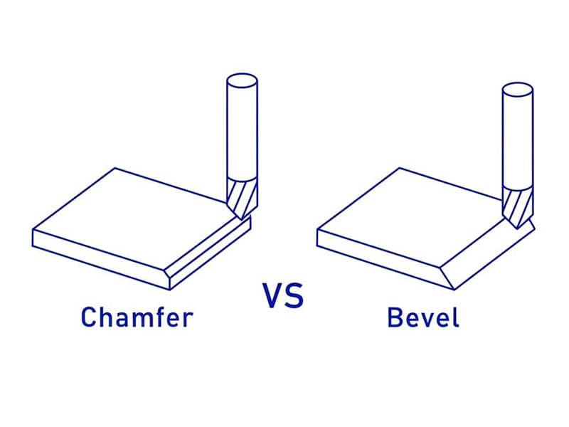
A chamfer replaces a sharp 90° edge with a small flat surface at an angle — most commonly 45°. It’s one of the most universal features in machined and fabricated parts.
Typical callout: C1.0 × 45° (1 mm chamfer at 45 degrees).
Functions: Removes sharp edges for safe handling. Provides lead-in for assembly (shaft into hole, fastener insertion). Creates thread start transition to prevent cross-threading. Minor stress concentration reduction at sharp corners. Standard sizes (C0.5, C1.0, C1.5) cover the vast majority of applications. Based on our production data, approximately 85% of chamfers we machine are C0.5 or C1.0 at 45° — standardizing on these two sizes across a product line reduces tool changes, simplifies programming, and cuts edge finishing cost by roughly 30% versus custom sizes on every feature.
What Is a Bevel?
A bevel is an inclined surface replacing a sharp edge — typically larger than a chamfer, with an angle that varies based on function (commonly 20°–45°). Unlike a chamfer’s small edge break, a bevel spans a significant surface area and serves a structural, joining, or aesthetic purpose.
Primary application: Welding preparation. Bevels create proper groove geometry (V-groove, single-bevel) that allows filler material penetration and ensures full-depth fusion. Typical weld bevel angles: 30°–37.5° per side. Without proper bevels on thick sections, welds risk incomplete penetration — producing joints that fail under load.
Other uses: Increased bonding area for adhesive joints. Structural load transitions between surfaces. Decorative edges on consumer products and architectural panels.
Key Differences
| Factor | Chamfer | Bevel |
|---|---|---|
| Size | Small edge break (C0.5–C2 typical) | Larger functional surface |
| Angle | Usually 45° (standardized) | Any angle (20°–45°+) |
| Purpose | Deburring, safety, assembly | Welding prep, bonding, aesthetics |
| CNC cost | Low (single pass, standard tools) | Higher (larger surface, precision angle) |
| Drawing callout | C × angle (e.g., C1 × 45°) | Angle + depth/length or weld spec |
| Structural impact | Minimal | Can affect joint strength, load path |
The distinction that matters: If the feature is small and only removes a sharp edge → chamfer. If it defines a functional surface or joint geometry → bevel. One common pitfall we see: drawings using “chamfer” and “bevel” interchangeably — causing suppliers to either under-machine (simple edge break where weld prep was needed) or over-machine (full bevel where deburring sufficed). Clear terminology prevents both errors.
Chamfer vs Bevel vs Fillet
| Edge Type | Shape | Best For | Stress Performance |
|---|---|---|---|
| Chamfer | Flat angled cut | Assembly, deburring | Minimal stress benefit |
| Bevel | Sloped surface | Welding, bonding, design | Moderate (load transition) |
| Fillet | Rounded radius | Fatigue resistance | Best (reduces Kt significantly) |
When geometry is curved → it’s a fillet, not a chamfer or bevel. Fillets reduce stress concentration far more effectively than chamfers — for fatigue-critical or high-load corners, a fillet radius is almost always the better engineering choice. Chamfers and bevels are flat features that don’t provide the same stress distribution benefit.
Selection logic: Edge safety/assembly → chamfer. Weld prep/bonding → bevel. Fatigue/stress-critical → fillet.
When to Use a Chamfer
Deburring and safe handling: Removes sharp edges from CNC machining, sheet metal cutting, and punching. Standard practice on virtually all machined parts.
Assembly lead-in: Guides shafts into holes, pins into bores, and fasteners into threads. Reduces insertion force and misalignment risk. Critical for automated assembly where self-alignment improves throughput.
Thread start: Chamfer at thread entry prevents cross-threading and improves tool engagement. Essential on both internal (tapped hole entry) and external threads.
Standard CNC edge finishing: Added during normal toolpath with minimal cycle time impact. Often the final operation before part completion. In our shop floor experience, adding C0.5 × 45° chamfers to all external edges of a typical CNC part adds approximately 15–30 seconds of cycle time — negligible cost for significant improvement in handling safety and assembly quality.
When to Use a Bevel
Welding preparation (primary use): Creates groove geometry for filler material penetration. V-groove (both sides), single-bevel (one side), or double-bevel (thick sections). Standard angles: 30°–37.5° per side per AWS/ISO specifications. Root face (land) and root gap must also be defined. Without proper bevel geometry, welds risk lack of fusion — the most dangerous weld defect because it’s invisible from the surface but compromises structural integrity.
Adhesive bonding: Larger surface area improves bond strength and load distribution. Common in composite structures and metal bonding applications.
Decorative/architectural edges: Controlled angled finish for consumer products, electronics housings, and architectural panels. Creates intentional visual edge lines that differ from simple edge breaks.
Structural transitions: Smooths load path between surfaces with different thicknesses or orientations.
CNC Machining Impact
| Factor | Chamfer | Bevel |
|---|---|---|
| Tooling | Standard chamfer mill/spot drill | May require custom angle setup |
| Programming | Simple (one pass) | More complex (larger surface) |
| Cycle time | Short (seconds) | Longer (depends on size) |
| Surface quality | Usually non-critical | May require Ra specification |
| Consistency | Easy across batches | Angle precision needs control |
Chamfers are CNC-friendly by default — one tool, one pass, minimal programming. Standard 45° chamfer mills are available in every shop. Bevels require explicit angle definition, potentially multi-axis machining for non-standard angles, and longer cycle times for larger surfaces. Surface quality on visible bevels may require additional finishing attention.
Batch production insight: Standardizing chamfer sizes (C0.5 and C1.0 only) across a product line eliminates tool changes between parts and reduces programming time. Multiple bevel variations increase setup complexity and reduce production efficiency. Based on our production data, parts with standardized chamfer specifications machine approximately 10–15% faster in batch production versus parts with mixed custom edge specifications.
Welding and Sheet Metal
Bevels are essential for welding. They provide the groove volume for filler material and heat penetration. Without proper bevel preparation, thick-section welds cannot achieve full fusion. Chamfers are too small to serve as weld grooves — they’re useful for pre-weld deburring and fit-up improvement, but don’t provide the geometry needed for structural welds.
Sheet metal: Bevels are used on thicker sheets requiring structural welds. Chamfers handle edge deburring after laser cutting, punching, or shearing. Both features improve safe handling of sharp cut edges.
How to Dimension on Drawings
| Feature | Callout Example | Notes |
|---|---|---|
| Standard chamfer | C1 × 45° | Size + angle (explicit) |
| Weld bevel | 30° ±2°, root face 1 mm | Angle + root face + standard |
| Edge break (non-critical) | Break sharp edges 0.1–0.3 | Generic deburring note |
| Decorative bevel | 30° × 3 mm, Ra 0.8 | Angle + depth + surface finish |
Chamfer dimensioning: Always specify size + angle for functional edges. “C1” alone is ambiguous if no company standard defines the default angle. Bevel dimensioning: Define angle AND linear size (depth or length). For weld prep, include root face, root gap, and applicable welding standard (AWS D1.1, ISO 9692, etc.). Edge break notes: “Break sharp edges 0.1–0.3” is acceptable only for non-critical edges. Never use generic notes for assembly-critical, sealing, or appearance edges.
Cost
Chamfers: Negligible cost impact. Standard tools, single-pass machining, minimal cycle time. The most cost-effective edge feature in manufacturing.
Bevels: Cost increases with size, angle precision, and surface requirements. Non-standard angles may require custom tooling or multi-axis positioning. Large bevels on thick plates may need flame/plasma cutting plus grinding. Visible bevels requiring consistent surface finish add finishing cost.
Cost control strategy: Default to standard chamfers (C0.5, C1.0 at 45°) for all non-functional edges. Specify bevels only where welding, bonding, or design requires them. Clear drawing callouts prevent supplier interpretation errors that inflate cost.
Decision Guide
| Need | Choose |
|---|---|
| Edge safety / deburring | Chamfer |
| Assembly lead-in | Chamfer |
| Thread start | Chamfer |
| Weld penetration | Bevel |
| Adhesive bonding area | Bevel |
| Decorative angled edge | Bevel |
| Fatigue-critical corner | Fillet (not chamfer or bevel) |
| Cost-sensitive standard edge | Chamfer (C0.5 or C1.0 × 45°) |
Conclusion
Chamfer and bevel both modify edges — but they serve different engineering purposes and carry different manufacturing costs. Chamfers are small, standardized 45° edge breaks for deburring, safety, and assembly — fast to machine, low cost, and standard on virtually every CNC part. Bevels are larger, angle-specific functional surfaces for welding preparation, bonding, structural transitions, and decorative design — requiring more machining time, explicit specification, and higher cost.
Clear specification prevents the most common and most expensive error: using the terms interchangeably and getting the wrong feature machined. Default to chamfers for standard edges. Specify bevels only when function demands them. Use fillets when stress or fatigue performance is the priority. Need help optimizing edge specifications for your CNC or fabricated parts? [Contact our engineering team] for DFM review and manufacturing support.
FAQ
What’s the difference between chamfer and bevel?
Chamfer is a small flat edge break (typically C0.5–C2 at 45°) for deburring and assembly. Bevel is a larger angled surface at any specified angle for welding preparation, bonding, or design. Chamfer = edge safety feature. Bevel = functional surface.
Is a chamfer the same as a bevel?
In broad terms, a chamfer is a type of beveled edge. In engineering drawings and manufacturing, they’re treated differently: chamfer is small and standardized, bevel is larger and function-defined. Using them interchangeably causes specification errors.
When should I use a fillet instead?
When the corner is fatigue-critical or under cyclic loading. Fillets (rounded radii) reduce stress concentration far more effectively than flat chamfers or bevels. For load-bearing corners, fillets are almost always the better choice.
Which costs more to machine?
Standard chamfers (C0.5, C1.0 × 45°) have negligible cost — single pass with standard tooling. Bevels cost more when they involve non-standard angles, larger surfaces, or surface finish requirements. Default to chamfers for cost-sensitive designs.
How should I dimension them on drawings?
Chamfer: C1 × 45° (size + angle). Bevel: 30° × 3 mm (angle + depth). Weld bevel: include angle, root face, root gap, and applicable standard. Never use generic “break edges” notes for functional or appearance-critical features.


