
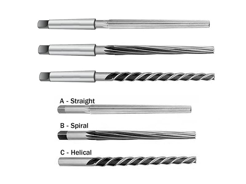
Quick Answer: A reamer is a multi-flute rotary tool that finishes a drilled hole to precise diameter, accurate roundness, and smooth surface finish by removing only 0.10–0.30 mm of material in a final controlled pass. Drilling establishes hole location and approximate size (typical tolerance ±0.05–0.10 mm); reaming achieves the functional tolerance — H7 fit, bearing seat, dowel pin hole — at ±0.010–0.025 mm with surface finish Ra 0.8–1.6 µm. The main types of reamers are: machine reamers (CNC production, ±0.010–0.025 mm repeatability), hand reamers (manual repair and single-part adjustment), carbide reamers (hard materials and high-volume production), helical flute reamers (tough materials like stainless steel where chip evacuation is critical), adjustable reamers (non-standard diameters), taper pin reamers (self-locking taper pin installations), shell reamers (large diameters), and floating reamer holders (correcting spindle misalignment). The correct selection depends on: required tolerance class, workpiece material, production volume, and whether the hole type is through or blind.
What Reamers Do — and Why Drilling Alone Is Insufficient
A drill creates a hole by fracturing and pushing material aside ahead of the two cutting lips at the drill point. The result is a hole that is approximately the right size and in the right location, but has limitations that are inherent to the drilling process:
Dimensional inaccuracy: Drills deflect slightly under the cutting forces, particularly when entering oblique surfaces, drilling in cross-holes, or working with long-reach tool setups. Even a sharp, correctly ground drill in good condition typically produces holes with diameter variation of ±0.025–0.075 mm and out-of-roundness (circularity error) of 0.025–0.075 mm.
Surface roughness: The drill’s cutting lips tear and scrape material rather than shearing it cleanly. The resulting bore surface is rough — Ra 3.2–6.3 µm is typical for drilled holes in steel, which is far coarser than the Ra 0.8–1.6 µm typically required for bearing seats, sliding fits, and hydraulic sealing bores.
These limitations are acceptable when the hole’s function is simply to pass a fastener — clearance holes for bolts, holes for cable routing, or holes that will be tapped. They are not acceptable when the hole must locate a component (dowel pin), support a rotating element (bearing), maintain a hydraulic seal (valve bore), or achieve a specific interference or clearance fit.
Reaming addresses all three limitations. A reamer’s multiple flutes (typically 4–8 for standard reamers) each remove a thin, even chip from the bore wall. The multi-flute contact with the existing bore wall guides the tool along the established centerline, correcting minor ovality and producing a bore that is consistently round. The light finishing chip load produces Ra 0.8–1.6 µm as a routine result. With appropriate tooling and process control, ±0.010–0.015 mm tolerance on hole diameter is achievable in production.
The stock allowance principle: Reamers are not designed to remove large amounts of material. If too much stock is left for reaming, the reamer deflects, produces chatter, and oversizes the hole. The standard practice is to drill the hole 0.10–0.30 mm undersize (depending on hole diameter and material) and then ream to final size. The reamer removes this final 0.10–0.30 mm total on diameter.
The Main Types of Reamers and Their Applications
Machine Reamers
Machine reamers are the standard production reaming tool for CNC machining centers, CNC lathes (for boring operations), and drill presses. They have a straight shank (cylindrical, for end-mill style holders) or a Morse taper shank for direct spindle mounting, and 4–8 straight or slightly spiral flutes.
Performance: Machine reamers used in CNC machining with appropriate rigidity, feed rate (approximately 0.1–0.4 mm/rev), and cutting speed (typically 50–80% of the drilling speed for the same material) produce bore tolerances of ±0.010–0.025 mm on diameter and surface finish of Ra 0.8–1.6 µm. These figures cover the majority of precision fit requirements in industrial manufacturing.
Material: High-speed steel (HSS) machine reamers are the standard for most steel and aluminum applications. Cobalt HSS (M42) provides better performance in austenitic stainless steel and high-nickel alloys. For high-volume production or hard materials, carbide (solid carbide or carbide-tipped) reamers are specified.
When to use: The default choice for CNC production of H7, H8, and comparable tolerance bores. Bearing seats, dowel pin holes in fixtures and tooling, locating bores in assembled components, and precision bushings are all routine applications.
Hand Reamers
Hand reamers have a square drive tang at the shank end (for tap wrench or T-handle) and a long, gently tapered lead-in chamfer that allows the tool to be guided manually into the bore without a machine. The flutes are typically slightly longer than machine reamers to accommodate the longer engagement needed for controlled hand operation.
Performance: Hand reaming depends on the skill and consistency of the operator. Tolerances of ±0.020–0.050 mm are achievable with careful technique; maintaining this across multiple parts in a production run is not practical. Hand reamers are inherently limited to situations where machine tooling is unavailable or impractical.
When to use: Field service and maintenance (enlarging or refining a hole in an assembly that cannot be disassembled to access a machine), fitting operations for press-fit or transition fits where final sizing must be done incrementally, and prototype/toolroom work where a single hole needs to be precisely sized. Hand reamers should not be used in production environments where hole-to-hole consistency is required.
Carbide Reamers
Carbide reamers use solid carbide construction (most common for small diameters, below approximately 16 mm) or carbide inserts brazed into a steel body (for larger diameters). Carbide’s modulus of elasticity (~550 GPa) is approximately 3× that of HSS (~200 GPa), producing less deflection under cutting loads and better dimensional stability — particularly relevant for deep bores and high-cutting-force materials.
Performance advantages over HSS: In abrasive materials (cast iron, fiber-reinforced plastics, hardened steel), carbide reamers last 5–15× longer than HSS reamers before the flute edges wear and diameter begins to drift. In continuous production runs (1,000+ holes), carbide reamers produce more consistent hole diameters throughout the run because wear affects the cutting diameter slowly and predictably. Carbide also permits higher cutting speeds, reducing cycle time.
When to use: Stainless steel (304, 316, duplex) where work hardening requires sharp, strong edges; titanium alloys where low thermal conductivity concentrates heat at the tool edge; hardened steels above approximately HRC 35; cast iron and other abrasive materials; and any high-volume application where per-hole cost justifies the higher carbide tool investment.
Helical Flute Reamers
Helical flute reamers have flutes that spiral around the body at a helix angle (typically 15–45°). This geometry produces a continuous, progressive cutting action (rather than the interrupted contact of straight flutes) and creates an axial chip-pumping effect that draws chips out of the bore toward the machine spindle in through-hole applications.
When straight flutes fail: In stainless steel and other work-hardening materials, straight flute reamers tend to produce chatter — the tool vibrates at the cutting edge contact frequency because the straight flute creates periodic impact loading. Helical flutes distribute the cutting force continuously around the bore, suppressing this vibration. The resulting bore surface is smoother (typically Ra 1.0–1.6 µm vs Ra 2.4–3.2 µm for straight flutes in stainless) and more dimensionally consistent.
Chip evacuation advantage: In deep bores (depth-to-diameter ratio above approximately 3:1) and in ductile materials that produce long, stringy chips (aluminum, copper, soft steel), the axial pumping action of helical flutes significantly reduces the risk of chip packing — accumulated chips jamming in the bore and scoring the finished surface or causing the reamer to seize.
When to use: Stainless steel (the primary application), copper and copper alloys, aluminum in deep-hole reaming, and any application where straight flute reamers have produced chatter or inconsistent surface finish.
Adjustable Reamers
Adjustable reamers have blade-type cutting inserts in angled slots that can be expanded or contracted to adjust the effective cutting diameter, typically over a range of ±0.5–2.0 mm from the nominal size. The adjustment is made by loosening a locking ring and advancing or retracting the blade inserts.
Precision limitations: The adjustable mechanism introduces additional variables (blade deflection, uneven adjustment between blades, runout from locking forces) that reduce achievable tolerance compared to solid reamers. Tolerances of ±0.025–0.050 mm are realistic with careful adjustment; ±0.010 mm is generally not achievable in routine practice.
When to use: Non-standard hole diameters not covered by standard fixed-size reamers; repair operations where the hole to be reamed has been worn or repaired to a non-standard size; and toolroom situations where the exact required size must be determined by trial. Not appropriate for tight-tolerance production applications.
Taper Pin Reamers
Taper pin reamers match the standard taper geometry of taper pins (defined by ASME B18.8 in the inch system: standard taper of 1:50 on diameter per unit length). The reamer’s cutting taper matches the taper of the pin, so the reamed hole receives the pin in a self-locking conical engagement.
Function: Taper pins provide a removable, self-tightening interference connection between a shaft and a mating part (hub, gear, lever). The conical engagement locks under axial force from assembly but can be driven out for disassembly. This is in contrast to cylindrical pins (including dowel pins), which rely on interference fit for retention.
When to use: Any assembly that uses standard taper pins per ASME B18.8 or equivalent metric standards. The reamed taper must match the specific taper pin number (#0 through #7 in the inch system, with corresponding taper diameters and lengths).
Shell Reamers
Shell reamers have a hollow body that mounts on an arbor, with the cutting teeth on the shell. The interchangeable shell concept allows the arbor to be reused when the shell is worn, reducing tooling cost for larger diameters where solid reamers are expensive.
When to use: Diameters above approximately 20–25 mm, where solid carbide reamers become prohibitively expensive and the shell reamer’s arbor-mounted design provides comparable rigidity at lower cost. Bearing housing bores, bushing bores in jig and fixture bodies, and large hydraulic bores are typical applications.
Floating Reamer Holders
A floating reamer holder (also called a floating chuck or flexible holder) is not a reamer type but a toolholding accessory that allows the reamer to float radially (typically ±0.5–2.0 mm total radial travel) relative to the machine spindle. This float compensates for misalignment between the drilled hole centerline and the spindle axis.
Why misalignment occurs: Even in well-calibrated CNC machining centers, the spindle axis and the drilled hole axis may not be perfectly coincident due to: drill deflection during the drilling operation (producing a hole that starts at the programmed location but deviates as it deepens), fixture registration errors, and thermal expansion of the machine structure. If a rigid reamer is driven down this slightly misaligned hole, the reaction forces cause the reamer to cut eccentrically, producing an oversized bore.
Floating holder compensation: The floating holder allows the reamer to follow the existing hole axis independently of the spindle axis, so the reamer cuts concentrically within the hole regardless of minor misalignment. The result is better roundness, more consistent diameter, and better surface finish compared to a rigid setup with the same degree of misalignment.
When to use: Precision production where hole concentricity below 0.010 mm TIR is required; thin-walled workpieces where reaction forces from a rigid setup would deflect the part; and any application where drilling consistently produces holes with minor departure from the programmed center.
Reamer Selection by Material
The workpiece material determines cutting forces, chip formation character, heat generation, and work-hardening tendency — all of which affect which reamer type performs best.
| Material | Recommended Reamer | Key Reason | Critical Parameter |
|---|---|---|---|
| Aluminum alloys | Straight flute machine reamer (HSS or carbide) | Simple geometry; adequate chip evacuation | High speed acceptable; avoid chip packing |
| Carbon steel (≤HB 250) | HSS machine reamer | Adequate wear resistance and toughness | Standard speeds and feeds |
| Austenitic stainless (304, 316) | Helical flute carbide reamer | Work-hardening; chip evacuation; chatter prevention | Reduced speed; steady, continuous feed |
| Hardened steel (>HRC 35) | Carbide reamer; CBN for >HRC 55 | Edge strength; wear resistance | Very low speed; rigid setup required |
| Titanium alloys | Carbide reamer; through-coolant preferred | Heat concentration at tool; abrasion | Very low speed; flood coolant |
| Cast iron | Carbide reamer | Abrasive wear from graphite inclusions | Moderate speed; compressed air chip clearing |
| Brass and bronze | HSS or carbide machine reamer | Low cutting forces; good surface finish | High speed; sharp edges to prevent tearing |
| Engineering plastics (PEEK, Delrin) | Sharp-geometry HSS or carbide | Prevent melting; clean chip removal | High speed; sharp edges; avoid heat buildup |
The stainless steel case in detail: Austenitic stainless steel (304, 316) work-hardens at the surface during cutting — each cutting pass leaves a harder layer that the next pass must cut through. With straight-flute reamers, the intermittent contact of each flute allows the workpiece material to spring back slightly between cutting events, exacerbating work-hardening and causing chatter. Helical flutes maintain more continuous contact, reducing spring-back and work-hardening rate. Combined with reduced cutting speed (approximately 50% of the speed used for carbon steel at equivalent diameter) and a continuous, steady feed that prevents the reamer from rubbing without cutting, helical carbide reamers produce clean, consistent bores in stainless that straight-flute HSS reamers cannot match.
Tolerances Achievable by Reamer Type
| Reamer Type | Typical Production Tolerance | Surface Finish (Ra) | Best Use Condition |
|---|---|---|---|
| Hand reamer | ±0.025–0.050 mm | Ra 1.6–3.2 µm | Single-part adjustment, repair |
| Machine reamer (HSS) | ±0.010–0.025 mm | Ra 0.8–1.6 µm | CNC production, standard materials |
| Machine reamer (carbide) | ±0.008–0.020 mm | Ra 0.4–1.2 µm | High-volume, hard materials |
| Helical flute reamer | ±0.010–0.025 mm | Ra 0.8–1.6 µm | Stainless, deep holes, chatter-prone |
| Adjustable reamer | ±0.025–0.050 mm | Ra 1.6–3.2 µm | Non-standard sizes, repair |
| Shell reamer | ±0.015–0.030 mm | Ra 1.2–2.4 µm | Large diameters |
| Carbide + floating holder | ±0.005–0.015 mm | Ra 0.4–0.8 µm | Highest precision production |
H7 tolerance as a design reference: H7 is the most common precision hole tolerance in ISO system drawings. For a 10 mm H7 bore, the tolerance is +0.015 / 0 mm (bore may be 10.000–10.015 mm). For a 20 mm H7 bore, the tolerance is +0.021 / 0 mm. A machine reamer used in a well-controlled CNC setup consistently achieves these tolerances across production batches.
Common Reaming Problems, Causes, and Solutions
| Problem | Primary Cause | Engineering Solution |
|---|---|---|
| Oversized hole | Reamer deflection; excessive speed; worn reamer | Reduce speed; use carbide reamer for rigidity; replace worn tool |
| Undersized hole | Insufficient stock allowance; worn reamer cutting undersize | Check pre-reaming diameter; use new reamer |
| Poor surface finish (Ra >3.2 µm) | Tool rubbing rather than cutting (dull edges, insufficient stock) | Verify pre-drill diameter leaves 0.10–0.30 mm; replace reamer |
| Chatter marks on bore wall | Machine vibration; straight flutes in work-hardening material | Use helical flute reamer; check machine and toolholder rigidity |
| Hole oversized at entry, tapering toward exit | Misalignment between spindle and hole; reamer deflecting | Use floating reamer holder; verify drill hole straightness |
| Chip packing (deep holes, aluminum) | Chips not evacuating; flute geometry trapping chips | Use helical flute reamer; increase coolant flow/pressure |
| Rapid tool wear | Wrong material for workpiece hardness | Upgrade from HSS to carbide; reduce cutting speed |
The pre-reaming allowance is the most common process error: If the drill leaves too little stock (less than approximately 0.050 mm total on diameter), the reamer cannot cut — it rubs, generating heat and pressure that may cause the bore to size correctly initially but produces a work-hardened surface and a short reamer life. If too much stock is left (above approximately 0.4–0.5 mm total for most materials), the reamer deflects under the load, producing an oversized hole with poor roundness. The 0.10–0.30 mm total stock allowance range is the window within which reaming functions correctly.
DFM Considerations for Reamed Holes
Standard reamer sizes: Reamers are manufactured to standard sizes (ISO 521, DIN 206, ASME B94.2 depending on the system). Designing hole diameters to match standard reamer sizes (increments of 0.5 mm at most diameters, with sub-0.5 mm sizes at small diameters) eliminates the need for custom or adjustable tooling. Non-standard hole diameters (e.g., 12.7 mm in a metric design context) require either an adjustable reamer or a custom-sized tool — both of which increase cost and reduce precision compared to standard sizes.
Reaming allowance accommodation: Engineering drawings that specify a final reamed diameter without accounting for the pre-reaming drill size can create manufacturing problems. Drawings should either specify the finish reamed diameter only (with a note such as “drill and ream to Ø10H7”) or specify both drill diameter and reamed diameter explicitly. The machinist’s responsibility is to select an appropriate drill size that leaves 0.10–0.25 mm stock for reaming.
Hole depth vs. diameter ratio: Reaming is straightforward for holes with depth-to-diameter ratio below approximately 3:1. Above 5:1, chip evacuation becomes problematic with straight flutes, and tool deflection reduces accuracy. Above 8:1, through-coolant (high-pressure coolant delivered through the tool center) becomes essentially mandatory for reliable chip evacuation, and maintaining positional accuracy requires careful attention to pre-drill straightness. Design drawings that specify deep, tight-tolerance bores should be reviewed for reaming feasibility.
Chamfer at bore entry: A 45° lead-in chamfer of 0.5–1.0 mm depth at the bore entry helps guide the reamer into the bore on the initial engagement pass, reducing the risk of the reamer chattering or deflecting at entry. This chamfer also breaks the sharp edge at the bore-face intersection, which is a stress concentration point in fatigue-loaded components.
Key Takeaways
- Reaming is the process that produces functional holes from drilled holes: the 0.10–0.30 mm stock removal in a reaming pass improves hole diameter accuracy from ±0.050–0.100 mm (drilled) to ±0.010–0.025 mm (reamed), and surface finish from Ra 3.2–6.3 µm (drilled) to Ra 0.8–1.6 µm (reamed).
- Machine reamers in CNC operations are the default choice for production tolerance bores: they achieve ±0.010–0.025 mm diameter tolerance with surface finish Ra 0.8–1.6 µm, covering H7 and comparable tolerance requirements in standard materials.
- Helical flute reamers are required for austenitic stainless steel and other work-hardening materials: straight flutes produce chatter in stainless because the intermittent contact allows material spring-back between cutting events; helical flutes maintain more continuous contact, suppressing chatter and producing Ra 1.0–1.6 µm consistently.
- Carbide reamers are required for high-volume production, hard materials, and applications requiring consistent bore diameter across thousands of holes: carbide lasts 5–15× longer than HSS in abrasive or work-hardening materials, maintaining diameter within tolerance for substantially longer production runs.
- Floating reamer holders compensate for spindle-to-hole misalignment: the floating compliance allows the reamer to follow the existing hole axis rather than being driven off-axis by the spindle, producing superior roundness and concentricity in high-precision applications.
- Pre-reaming stock allowance of 0.10–0.30 mm total on diameter is critical: too little stock causes rubbing and work hardening; too much causes deflection, oversize, and chatter.
- For OEM procurement and design teams: specify reamed holes as “drill and ream Ø[nominal] [tolerance class]” (e.g., “drill and ream Ø10H7”) rather than specifying only the final diameter without process context. This gives the machining supplier clear instruction on the required tolerance and implies the two-step process. For stainless steel or titanium components with precision bores, specifying “reamed, helical flute carbide tooling” in the process note avoids the straight-flute problems that result in rework.
Frequently Asked Questions
What is the difference between a machine reamer and a hand reamer?
A machine reamer is designed for use in a CNC machining center, drill press, or lathe at controlled speed and feed, and produces consistent hole tolerances of ±0.010–0.025 mm with surface finish Ra 0.8–1.6 µm across production batches. A hand reamer is turned manually with a tap wrench or T-handle, has a long taper lead-in for guided entry, and produces tolerances of ±0.025–0.050 mm that vary with operator technique. Machine reamers are the correct choice for any situation requiring consistent, repeatable results across multiple parts. Hand reamers are appropriate for repair and maintenance when machine access is not available, or for single-part fitting operations where size must be adjusted incrementally by feel.
Why should a helical flute reamer be used for stainless steel?
Austenitic stainless steel (304, 316) work-hardens when cut — the surface of the material becomes harder than the underlying material after each cutting pass, requiring subsequent passes to cut through progressively harder material. With straight-flute reamers, each flute contacts the bore wall briefly and then loses contact before the next flute engages. During this no-contact interval, the material surface springs back and partially work-hardens. When the next flute engages, it encounters a harder surface, creating a chatter-inducing interrupted cutting action. Helical flutes maintain more continuous contact with the bore wall throughout the cutting pass, reducing the spring-back interval and suppressing chatter. The result is Ra 0.8–1.6 µm bore finish in stainless compared to Ra 2.4–3.2 µm or worse with straight flutes.
How much stock should be left for reaming?
The standard pre-reaming stock allowance is 0.10–0.30 mm total on diameter (0.05–0.15 mm per side), scaled toward the lower end for small diameters and soft materials, and toward the upper end for large diameters and hard materials. For a Ø10 mm hole in steel, 0.10–0.15 mm total stock (drill to Ø9.85–9.90 mm, ream to Ø10.000 mm H7) is standard. If less stock is left, the reamer cannot cut cleanly and will rub rather than shear, generating heat, work-hardening the bore surface, and reducing reamer life. If more stock is left, the reamer deflects under the higher cutting load, producing an oversized hole with poor roundness. Verifying pre-drill diameter before each reaming operation is a basic quality control step in precision machining.
When should a floating reamer holder be used?
A floating reamer holder is used when there is misalignment between the spindle axis and the drilled hole centerline that cannot be corrected by machine setup. This misalignment occurs when the drill deflects during drilling (producing a hole with a centerline that deviates from the programmed path), when fixture registration errors place the hole off-axis relative to the spindle, or when thermal expansion of the machine changes the relationship between the spindle and fixture during the production run. Without a floating holder, a rigid reamer driven into a misaligned hole produces an eccentric cut — the reamer removes more material on one side than the other — resulting in an oversized bore and poor roundness. The floating holder allows the reamer to follow the existing hole axis, producing roundness within 0.005–0.010 mm TIR in applications that rigid setups cannot achieve.
What tolerance can CNC reaming achieve?
Standard CNC machine reaming with HSS tooling achieves ±0.010–0.025 mm on bore diameter and Ra 0.8–1.6 µm surface finish, which covers H7 and H8 ISO tolerance requirements at most diameters. Carbide reamers in rigid setups achieve ±0.008–0.020 mm. Carbide reamers with floating holders achieve ±0.005–0.015 mm and Ra 0.4–0.8 µm. These figures assume: correct pre-reaming stock allowance (0.10–0.30 mm total), appropriate cutting speed (50–80% of drilling speed for the same material), and a reamer in good condition (sharp flutes, within diameter specification). Tool wear causes progressive diameter drift — a reamer that held ±0.012 mm at the start of a production run may produce bores at ±0.025 mm after significant wear. Monitoring bore diameter through the production run and replacing the reamer before tolerance is exceeded is essential for consistent production quality.
Written by the CMS engineering team with 15+ years of precision CNC machining experience producing reamed bores for bearing seats, dowel pin holes, hydraulic components, aerospace bushings, and medical device assemblies in aluminum, stainless steel, titanium, and engineering alloys. Technical references: Machinery’s Handbook (Reamers and Reaming), ASME B94.2 (Reamers), ISO 521 (Hand Reamers — Dimensions), Sandvik Coromant Hole-Making Application Guide, SME Fundamentals of Tool Design (Reaming chapter).
Sourcing Precision CNC Machined Components Requiring Reamed Bores?
At CMS, we produce precision reamed holes to H7, H6, and custom tolerance specifications — with material-appropriate tooling (helical flute carbide for stainless, floating holders for high-precision production), CMM bore measurement on first articles, and process capability documentation.
[Request a reamed hole specification review and CNC machining quote →]


