
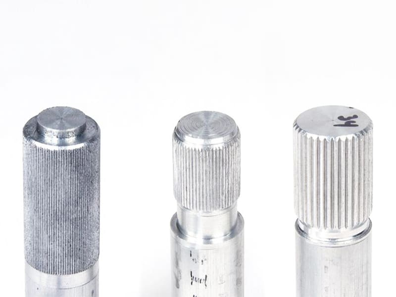
Quick Answer: Straight knurling produces parallel ridges running axially or circumferentially on a cylindrical surface — unlike diamond knurling (which crosses ridges in both directions), straight knurling provides controlled, directional grip rather than maximum multi-directional traction. It is the correct choice for press-fit inserts into plastic or aluminum housings (where diamond knurl creates excessive stress and cracking risk), precision adjustment components (where controlled tactile feedback matters more than maximum grip), and parts in clean or hygienic environments (where straight grooves clean more easily than cross-hatched diamond patterns). The most critical design parameter is matching pitch to part diameter — when pitch does not evenly divide the circumference, double tracking (overlapping patterns) occurs, producing a cosmetically and functionally defective knurl. Typical straight knurl pitch is 0.5–2.0 mm; knurling increases outer diameter by +0.05–0.2 mm, which must be accommodated in the pre-knurl machined dimension.
What Is Straight Knurling?
Straight knurling is a surface forming process that creates parallel ridges along the axis of a cylindrical part by pressing hardened knurl wheels against the rotating workpiece on a lathe. The ridges are formed by plastic deformation of the workpiece material — the knurl wheel displaces material outward rather than cutting chips, which is why the process increases the outer diameter slightly.
The geometry: parallel linear ridges running along the part’s axis (axial straight knurl) or around the circumference (circumferential straight knurl). No crossing pattern — the defining characteristic that separates straight knurling from diamond knurling. The clean, parallel line pattern gives straight knurled parts a more technical, controlled aesthetic and, more importantly, provides friction that acts preferentially in one direction.
This directional friction characteristic is the engineering rationale behind most straight knurling specifications. An axially straight-knurled shaft resists axial pull-out while allowing some rotational slip — useful for shafts that must resist extraction but accommodate rotational adjustment. A circumferentially straight-knurled knob resists rotation while allowing axial translation.
Straight Knurling vs Diamond Knurling: Engineering Comparison
The two knurling patterns are not interchangeable — they serve different functional objectives.
| Feature | Straight Knurling | Diamond Knurling |
|---|---|---|
| Ridge geometry | Parallel (linear, one direction) | Cross-hatched (two directions) |
| Grip direction | Directional — one axis | Multidirectional |
| Grip intensity | Controlled, moderate | Aggressive, maximum |
| Press-fit behavior | Predictable interference, lower stress | Higher retention force, greater material stress |
| Cleaning and maintenance | Easy — open linear grooves | Harder — cross-pattern traps debris |
| Appearance | Clean, technical | Aggressive, textured |
| Risk to soft mating materials | Lower | Higher (cracking in plastics/aluminum) |
| Typical applications | Press-fit inserts, precision adjustments | Hand tools, maximum-grip handles |
The decision framework: select straight knurling when controlled interaction, directional friction, or material stress minimization governs; select diamond knurling when maximum grip in all directions is the overriding requirement.
A common engineering mistake is defaulting to diamond knurling because “it grips better” — in many applications, excessive grip causes problems: stress concentration in press-fit mating materials, reduced comfort in frequently-handled controls, and difficulty cleaning in food or medical environments.
Applications Best Suited to Straight Knurling
Press-Fit Inserts
Press-fit applications represent the most engineering-critical use of straight knurling. The objective is not simply holding the insert — it is producing consistent, predictable insertion force across production batches while minimizing stress in the mating material.
Straight knurling’s parallel ridges displace mating material in a single direction during press insertion, creating predictable deformation and allowing the insertion force to build gradually and consistently. Diamond knurling’s crossed ridges push material in multiple directions simultaneously, creating higher local stress and less predictable force variation between parts.
For press-fits into plastic housings (ABS, PC, Nylon, acrylic), this difference is often the difference between successful assembly and cracked housings. Diamond-knurled brass inserts into polycarbonate enclosures produce inconsistent insertion force and occasional cracking; straight-knurled inserts produce consistent, lower peak force without cracking.
For production: straight knurling allows tighter control of insertion force specification (e.g., 200–350 N), enabling assembly process validation and statistical process control. Diamond knurling in the same application may produce insertion force variation of ±50% between parts, making force-controlled assembly unreliable.
Precision Adjustment Components
Thumbscrews, calibration dials, micrometer thimbles, focus rings, aperture adjusters, collimator adjustments, and similar precision control components benefit from straight knurling for two reasons:
Tactile feedback control: Diamond knurling’s aggressive peaks create a “grip-or-slip” interaction. Straight knurling’s gentler ridges provide a more refined rotational feel with consistent tactile feedback per degree of rotation — important when the user is making fine adjustments with controlled force.
Dimensional predictability: Precision instruments are designed to close tolerances. The more controlled deformation profile of straight knurling on precision components allows tighter dimensional control of the final surface.
Medical and Food Processing Equipment
Parts in these environments face competing requirements: adequate grip for operation and easy cleaning for hygiene compliance.
Diamond knurling’s crossed grooves trap particles, oils, biological residue, and cleaning agent residue — the intersections of the cross-pattern are effectively blind pockets that cleaning cloths cannot reach. Straight knurling’s parallel open grooves allow a cloth or cleaning implement to pass along the groove length, removing residue effectively.
For parts that contact food (handles on portioning equipment, gripping surfaces on food processing machine components) or must be sterilized (surgical instrument handles, medical device grips), straight knurling complies more readily with surface hygiene requirements.
Anti-Rotation and Anti-Withdrawal Shaft Connections
Straight knurling on a shaft that is pressed into a housing creates directional resistance: the ridges resist axial extraction (parallel to the ridge axis) while providing limited torsional resistance. This characteristic is exploited in shaft-collar assemblies, motor shaft-to-impeller connections, and indexing pins where controlled resistance in one axis is the design requirement.
Design Parameters: What Controls Knurling Quality
Pitch-Diameter Relationship (The Most Critical Parameter)
The most common straight knurling defect — double tracking — is entirely a design issue, not a machining issue. Double tracking occurs when the knurl pitch does not divide evenly into the circumference of the part.
The relationship: for a part with outer diameter D (mm) and knurl pitch P (mm), the number of ridges N = π × D / P. For a clean, non-overlapping knurl pattern, N must be an integer — if π × D / P is not a whole number, the knurl wheel cannot return to the same starting position after one revolution, and the ridges overlap on subsequent passes, producing the characteristic “ghost” double-tracking pattern.
Practical design approach:
- Choose the desired pitch P for the functional requirement
- Calculate the target diameter: D = (N × P) / π, where N is the nearest integer
- Machine the pre-knurl diameter to this calculated value
If the designer specifies a part diameter based on other dimensional requirements that does not satisfy this relationship, one of three accommodations is required: adjust the diameter slightly (often a change of 0.1–0.3 mm is sufficient to find a compatible diameter), change the pitch, or accept a slightly non-perfect pattern (which may be acceptable for non-critical applications but not for precision or decorative ones).
Typical Pitch Ranges
| Pitch Range | Ridge Count for 10 mm OD | Grip Character | Typical Application |
|---|---|---|---|
| 0.5 mm | ~63 ridges | Fine, subtle | Precision instruments, optical components |
| 0.8 mm | ~40 ridges | Light grip | Calibration dials, adjustment knobs |
| 1.0 mm | ~31 ridges | General purpose | Thumbscrews, press-fit inserts |
| 1.5 mm | ~21 ridges | Moderate grip | Machine handles, adjustment collars |
| 2.0 mm | ~16 ridges | Coarse grip | Heavy-duty handles, industrial components |
Knurl Depth and Outer Diameter
Knurling displaces material outward — the ridges formed are raised above the original surface. Typical outer diameter increase from knurling is +0.05–0.2 mm depending on pitch, material, and forming pressure. This must be accommodated in the machined pre-knurl dimension.
Incorrect approach: Machine part to final nominal OD, then knurl → part is now oversized by the knurl displacement amount.
Correct approach: Calculate required pre-knurl OD as: D_pre-knurl = D_final − ΔD_knurl, where ΔD_knurl is the expected diameter increase from knurling (typically 0.05–0.15 mm for aluminum and brass, 0.10–0.20 mm for steel). Machine to D_pre-knurl, then knurl to achieve D_final.
For press-fit applications where the interference depends on the knurled OD, the pre-knurl diameter and final knurled OD must both be specified on the drawing — not just one or the other.
Knurl depth vs grip and insertion force: Deeper knurls provide stronger grip and higher press-fit retention force, but also create greater material deformation in the mating part. For press-fits into plastic or aluminum, shallower knurls (ridge height 0.05–0.12 mm) with consistent pitch produce better controlled insertion force than deep knurls. For metal-to-metal press fits requiring maximum retention, deeper knurls (ridge height 0.15–0.25 mm) are appropriate.
Edge Chamfers and Relief Features
Knurling that starts abruptly at a shoulder or edge creates several problems: the knurl wheel slips on initial contact, the first few ridges are poorly formed, and the edge deformation can interfere with adjacent features. Two design solutions:
Entry chamfer: A small chamfer (0.5–1.0 mm × 45°) at the knurl entry point allows the knurl wheel to engage progressively. The chamfer breaks any shoulder corner that would prevent proper tool engagement.
Relief groove: A narrow relief groove (typically 1–2 mm wide, 0.3–0.5 mm deep) located at the end of the knurled zone before an adjacent precision surface prevents knurl deformation from propagating into the precision surface.
Material Selection for Straight Knurling
Straight knurling is a plastic deformation process — the material must be ductile enough to accept displacement without tearing. Material choice governs the quality and consistency of the knurl pattern.
| Material | Knurl Quality | Forming Ease | Ridge Sharpness | Tool Wear | Notes |
|---|---|---|---|---|---|
| Aluminum 6061/6063 | Excellent | Easy | Sharp, clean | Very low | Best all-around choice for knurled parts |
| Brass (C36000) | Excellent | Very easy | Very crisp | Very low | Easiest to knurl; best cosmetic result |
| Mild steel (1018, 1020) | Good | Moderate | Good | Moderate | Standard for steel knurled components |
| Stainless steel (304) | Moderate | Hard | Variable | High | Requires higher tool pressure; risk of tearing |
| 316 stainless steel | Moderate | Hard | Variable | Higher | Similar to 304 but more work-hardening |
| Titanium | Difficult | Very hard | Inconsistent | Very high | Only where material properties mandate it |
| Delrin (POM) | Moderate | Easy | Soft edges | Low | Low grip strength; light-duty applications only |
| Nylon (PA) | Moderate | Easy | Soft, fuzzy edges | Low | Similar to Delrin; moisture sensitivity relevant |
Aluminum is the preferred material for most straight knurling applications — ductile enough to form clean, sharp ridges with low forming force, resulting in consistent patterns across production runs with minimal tool wear.
Brass produces the finest cosmetic knurl quality of any common engineering material because of its excellent ductility and surface finish characteristics after deformation. Precision instrument components and decorative-functional hardware frequently specify brass for this reason.
Stainless steel requires significantly higher forming pressure and produces more variable results. For applications where corrosion resistance mandates stainless, the knurling process requires more rigid setup, reduced forming depth, and more careful control of feed and speed to avoid ridge tearing and inconsistent depth.
Plastics can be knurled but the ridges are soft, have lower grip performance, and wear faster than metal. Knurling of plastics is appropriate only for light-duty applications where the knurl provides tactile identification rather than functional grip.
Drawing Specification Requirements
A knurl callout of simply “KNURL” is not a specification — it is an instruction that will produce unpredictable results across different suppliers. Complete straight knurl drawing specifications must include:
Required elements:
| Drawing Requirement | Example | Engineering Purpose |
|---|---|---|
| Pattern type | STRAIGHT KNURL | Prevents confusion with diamond or other patterns |
| Pitch | PITCH 1.0 mm | Controls pattern quality; enables pitch-diameter compatibility check |
| Pre-knurl diameter | Ø9.82 ±0.02 mm (PRE-KNURL) | Allows supplier to achieve target final OD |
| Final OD after knurling | Ø10.00–10.08 mm | Controls fit and interference for press-fit |
| Knurl length | 12 mm | Defines functional zone |
| Location | 2 mm FROM SHOULDER | Prevents interference with precision surfaces |
| Orientation (if relevant) | AXIAL or CIRCUMFERENTIAL | Clarifies ridge direction |
Example complete callout:
STRAIGHT KNURL, PITCH 1.0 mm, LENGTH 12 mm, 2 MM FROM SHOULDER
PRE-KNURL Ø: 9.82 ±0.02 mm
FINAL KNURLED OD: Ø10.00–10.08 mm
Tolerance Considerations for Knurled Surfaces
Knurled surfaces are formed, not machined to dimensional tolerance. Applying tight tolerances (e.g., ±0.01 mm) to a knurled OD is not appropriate — the irregular surface texture means that any diameter measurement will vary depending on where the calliper contacts relative to the ridges. Functional tolerance for knurled surfaces should specify a range (e.g., Ø10.00–10.08 mm) rather than a bilateral tolerance, and the range should accommodate the forming variation inherent in the process.
For press-fit applications, the functional specification is the interference range — the difference between the knurled OD and the housing bore diameter. Specifying this interference range explicitly (e.g., “interference with Ø10.00 +0.000/−0.020 mm housing bore: 0.00–0.08 mm”) is more useful than specifying the knurled OD alone.
Common Knurling Defects and Root Causes
| Defect | Appearance | Root Cause | Corrective Action |
|---|---|---|---|
| Double tracking | Overlapping “ghost” pattern | Pitch does not divide evenly into circumference | Recalculate diameter to match pitch; or change pitch |
| Torn knurls | Rough, broken, ragged ridges | Excessive forming pressure; material too hard or brittle | Reduce depth; increase forming passes; evaluate material |
| Flattened ridges | Rounded, weak, indistinct peaks | Insufficient forming pressure; worn knurl wheel | Increase pressure; replace wheel |
| Uneven depth | Variable ridge height across length | Tool misalignment; machine deflection; workpiece runout | Improve setup rigidity; check alignment; reduce speed |
| Chatter marks | Wavy, periodic variation in pattern | Vibration; insufficient machine rigidity; incorrect feed | Reduce overhang; increase rigidity; adjust feed rate |
| Poor start/end definition | Ragged entry or exit ridges | No chamfer or relief at knurl boundary | Add entry chamfer or relief groove |
Most knurling defects are preventable through correct design — particularly the pitch-diameter relationship — and proper setup. The defect pattern most often encountered in production (double tracking) is almost always a consequence of specifying a diameter that was not checked for pitch compatibility.
Straight Knurling vs Other Grip Surface Options
When evaluating whether straight knurling is the right solution, consider alternative surface treatments that may better match specific requirements:
| Surface Treatment | Grip Level | Feel | Cleanability | Cost | Best Application |
|---|---|---|---|---|---|
| Straight knurling | Controlled, directional | Technical, precise | Easy (linear grooves) | Low | Precision handling, press-fits |
| Diamond knurling | High, multidirectional | Aggressive | Poor (cross-hatch traps debris) | Low | Maximum-grip hand tools |
| Rubber overmolding | High | Soft, comfortable | Medium | High | Ergonomic grips |
| Milled texture/pattern | Medium, customizable | Custom | Good | Medium-High | Aesthetic-performance balance |
| Laser surface texturing | Medium, controlled | Fine, detailed | Good | High | Brand + grip combination |
| Cut grooves (machined) | Low to medium | Simple, functional | Excellent | Very Low | Cost-sensitive, simple grip |
Key Takeaways
- Straight knurling provides directional, controlled grip — not maximum traction in all directions. This makes it superior to diamond knurling for press-fits into soft materials, precision control components, and cleanable surfaces.
- The pitch-diameter compatibility calculation is mandatory for any knurling specification: N = π × D / P must yield a whole number, or double tracking will occur. This is a design calculation, not a machining adjustment.
- Knurling increases outer diameter by +0.05–0.2 mm through material displacement — the pre-knurl machined dimension must be reduced by the expected displacement amount to achieve the target final OD.
- Best materials for straight knurling are aluminum and brass — both produce clean, sharp, consistent patterns with low forming force. Stainless steel requires more force and process control; plastics produce soft ridges with limited functional grip.
- Drawing callouts must include: pattern type (straight), pitch (mm), pre-knurl diameter, final OD range, knurl length, and location — omitting any of these produces unpredictable results across suppliers.
- Entry chamfers and relief grooves at knurl boundaries prevent edge deformation and protect adjacent precision surfaces from contamination by knurling displacement.
- For OEM procurement teams: straight knurling specifications should always be validated by the supplier for pitch-diameter compatibility before production begins. A supplier who does not verify this relationship will produce double-tracked parts that are cosmetically defective and may have reduced grip performance.
Frequently Asked Questions
What is straight knurling used for?
Straight knurling is used to add controlled, directional friction or grip to a cylindrical part. Primary functional applications are: press-fit inserts (where the parallel ridges create predictable interference as the part is pressed into a housing, with lower cracking risk than diamond knurling in soft mating materials), precision adjustment components (thumbscrews, calibration dials, focus rings, where controlled tactile feedback and moderate grip are required), and components in clean or hygienic environments (where the open parallel grooves clean more easily than diamond’s cross-pattern). It is also used for anti-rotation retention of shafts and pins where directional friction control — rather than maximum grip — is the design objective.
What is the difference between straight and diamond knurling?
The ridge geometry defines the functional difference. Straight knurling produces parallel ridges in one direction (typically along the axis), providing directional grip that acts in one axis. Diamond knurling produces ridges running in two crossing directions, creating a cross-hatched pattern that grips in all directions. Diamond knurling produces higher friction and greater grip force under most loading conditions, but also creates higher stress in mating materials during press insertion, generates more debris-trapping intersections in the groove pattern, and creates a more aggressive tactile feel. Straight knurling is the correct choice when controlled interaction, ease of cleaning, or reduced mating material stress governs. Diamond knurling is correct when maximum grip is the overriding requirement.
Why does double tracking happen in knurling?
Double tracking occurs when the knurl pitch does not divide evenly into the part circumference. When a knurl wheel makes one full revolution around the part, it must return to exactly the same starting position — otherwise the ridges from the second pass overlap slightly with the first pass, producing a blurred “ghost” pattern of overlapping ridges. The root cause is always a design issue: the combination of diameter and pitch chosen by the designer does not satisfy the integer relationship N = π × D / P. The solution is to recalculate the target diameter for the chosen pitch (or choose a pitch that satisfies the relationship at the intended diameter), not to adjust machining parameters. Double tracking cannot be fixed by changing speed, feed, or forming pressure.
What is the correct way to specify straight knurling on a drawing?
A complete knurling callout must include: pattern type (STRAIGHT KNURL), pitch in millimeters (e.g., PITCH 1.0 mm), pre-knurl diameter (the machined OD before knurling, with tolerance), final knurled OD range (functional range after knurling, not bilateral tolerance), knurl length, and location relative to a datum or feature. For press-fit applications, also specify the acceptable interference range with the mating bore. A callout of just “KNURL” is insufficient — it does not specify pattern type, pitch, or dimensional requirements, and different suppliers will interpret it differently, producing inconsistent results.
How much does knurling increase part diameter?
Straight knurling increases the outer diameter through outward material displacement, typically by +0.05–0.2 mm depending on pitch, material, and forming pressure. Aluminum and brass with 1.0 mm pitch typically produce +0.08–0.12 mm increase; steel with the same pitch produces +0.10–0.18 mm increase; deeper pitches (1.5–2.0 mm) produce larger diameter increases. The pre-knurl machined diameter must be reduced by this expected amount — if the designer specifies a final knurled OD of 10.00–10.05 mm and the expected diameter increase from knurling is 0.10 mm, the machined pre-knurl diameter should be approximately 9.90 mm ±0.02 mm. This pre-knurl diameter should appear explicitly on the engineering drawing.
Written by the CMS engineering team with 15+ years of precision CNC turning experience producing knurled shafts, press-fit inserts, adjustment knobs, and precision instrument components in aluminum, brass, mild steel, and stainless steel for industrial, medical, electronics, and automotive OEM manufacturing applications. Technical references: ASME B46.1 (Surface Texture), ISO 13715 (Indication of Surface Texture), ASME Y14.5-2018 (Geometric Dimensioning and Tolerancing), Machinery’s Handbook (Knurling — Pitch and Diameter Calculations).
Sourcing CNC Turned Components With Straight Knurling?
At CMS, we produce straight-knurled press-fit inserts, precision adjustment knobs, thumbscrews, and knurled shafts in aluminum, brass, and steel — with pitch-diameter compatibility verification, pre-knurl and post-knurl dimension control, and drawing review for chamfer and relief requirements before production begins.
[Request a knurling specification review and CNC turning quote →]


