
Quick Answer: Effective heat sink design starts with thermal resistance calculation — not fin geometry. The required heat sink thermal resistance is: R_sa = (Tj_max − Ta) / Q − R_jc − R_TIM, where Tj_max is the maximum junction temperature, Ta is the worst-case ambient, Q is peak power dissipation, R_jc is junction-to-case resistance, and R_TIM is the interface material resistance. Once the target R_sa is known, the design optimizes six variables in sequence: airflow type (natural or forced convection), fin spacing, base thickness, fin height, surface area, and material. The single most common heat sink design failure is misaligned or blocked airflow — a correctly sized aluminum heat sink in well-managed airflow will outperform a copper heat sink in poor airflow every time.
Why Heat Sinks Fail Despite Looking Right
The most reliable engineering insight about heat sink design is also the most counterintuitive: a heat sink that looks oversized in simulation frequently fails in the real product. The reason is that thermal simulation models the heat sink in isolation, while the product installs it in an enclosure with restricted airflow, elevated ambient temperature from adjacent heat sources, and a thermal interface applied by assembly operators rather than ideal conditions.
The most common real-world failure modes are:
Fin spacing too tight for available airflow: Dense fins increase surface area on paper. In a compact enclosure with a small fan, they may reduce actual cooling by increasing airflow resistance beyond what the fan’s pressure capability can overcome. In one of our production cases with a compact industrial controller, reducing fin spacing from 2.5 mm to 1.5 mm (to increase surface area) actually raised steady-state temperature by 7°C because the fan’s static pressure was insufficient to maintain airflow through the tighter fin stack.
Enclosure trapping hot air: A heat sink drawing ambient air from a sealed enclosure recycles the same heated air, causing ambient temperature to rise over time. A correctly calculated heat sink thermal resistance at 25°C ambient may be 50–100% too small at 50°C ambient inside a poorly ventilated cabinet.
Thermal interface failures: The purpose of thermal paste is to eliminate microscopic air gaps — not to “cool” the chip. Correct application is a thin layer (approximately 0.05–0.15 mm), barely enough to fill surface irregularities. Thick application increases thermal resistance. Pump-out during thermal cycling (caused by mismatched coefficients of thermal expansion between components) allows air gaps to reopen.
Insufficient base thickness for heat spreading: A thin base plate concentrates heat directly above the source. Only the fins directly above the contact zone contribute meaningfully to cooling; outer fins remain relatively cool and are thermally wasted. A 4 mm aluminum base under a 50W module may leave the contact zone 15–20°C hotter than a 10 mm base, with no change in fin design.
The Thermal Path: What Heat Actually Does
Heat does not jump from the chip into the air — it follows a specific path, and the resistance at each stage determines the temperature at the chip junction.
Stage 1 — Conduction from chip to heat sink base: Heat conducts through solid materials: junction → chip package → thermal interface material (TIM) → heat sink base. This stage is governed by material thermal conductivity, interface contact quality, mounting pressure, and surface flatness. A warped mating surface can increase junction temperature by 5–15°C even with a large heat sink, because the microscopic air gaps created by the warp are poor thermal conductors.
Stage 2 — Spreading through the base: Heat distributes laterally through the aluminum or copper base from the contact zone to the full fin area. The spreading resistance depends on base thickness, base material conductivity, and the ratio of contact area to total base area. This stage is where thin aluminum bases fail for high-flux sources.
Stage 3 — Convection from fins to air: Heat transfers from fin surfaces to moving (or still) air through convection. This is the stage that determines most of the practical performance difference between designs — not material conductivity. The convective heat transfer coefficient h (W/m²·K) for natural convection is 5–15 W/m²·K; for forced convection at typical fan velocities of 1–3 m/s, h reaches 30–100 W/m²·K or higher. The ratio explains why forced convection can improve performance by 3–7× over natural convection with the same heat sink geometry.
Thermal Resistance Calculation: How to Size a Heat Sink
The Core Formula
All heat sink sizing begins with the thermal resistance required from the heat sink. The relationship between power, temperature, and resistance is:
R_total = (Tj_max − Ta) / Q
Where:
- Tj_max = maximum allowable junction temperature (°C) from the device datasheet
- Ta = worst-case ambient temperature (°C) — use the actual expected operating environment, not a laboratory value
- Q = peak power dissipation (W) — include startup transients and worst-case operating load, not average power
- R_total = total allowed thermal resistance from junction to ambient (°C/W)
The total resistance is divided among the stages of the thermal path:
R_total = R_jc + R_TIM + R_sa
Where:
- R_jc = junction-to-case thermal resistance (from device datasheet)
- R_TIM = thermal interface material resistance (from TIM manufacturer data, typically 0.05–0.30 °C/W·cm² ÷ contact area)
- R_sa = required heat sink-to-ambient thermal resistance (the design target)
Therefore:
R_sa = R_total − R_jc − R_TIM
Worked Example
System parameters:
- IGBT module, Tj_max = 125°C
- Installed ambient temperature = 50°C (worst-case industrial cabinet)
- Peak power = 80W
- R_jc from datasheet = 0.30 °C/W
- R_TIM (20 µm silicone pad, 60 cm² contact) = 0.20 °C/W
Calculation:
R_total = (125 − 50) / 80 = 0.94 °C/W
R_sa = 0.94 − 0.30 − 0.20 = 0.44 °C/W
This R_sa of 0.44 °C/W is an aggressive target requiring forced air cooling. Natural convection aluminum heat sinks typically achieve R_sa of 1.5–5.0 °C/W; forced convection aluminum heat sinks can reach 0.3–1.5 °C/W depending on airflow velocity and heat sink geometry.
Interpreting the R_sa Target
| Required R_sa (°C/W) | Typical Implication |
|---|---|
| > 3.0 | Natural convection may suffice with adequate fin area |
| 1.0–3.0 | Natural convection with larger heat sink or enhanced passive design |
| 0.5–1.0 | Forced convection typically required; depends on airflow |
| 0.2–0.5 | Forced convection required; careful airflow design needed |
| < 0.2 | Liquid cooling or high-performance forced air system required |
Why Real Performance Differs from Datasheet Performance
Heat sink datasheets specify thermal resistance under controlled laboratory conditions: uniform, unobstructed airflow at a stated velocity, stable ambient temperature, optimal thermal interface. In a real product enclosure:
- Airflow through the fins may be 30–60% of the design velocity due to enclosure restrictions, cable routing, and proximity to walls
- Ambient temperature inside the enclosure may be 15–25°C higher than external ambient due to self-heating of surrounding components
- Thermal interface quality varies with assembly technique and changes over time through thermal cycling
A conservative design practice: calculate R_sa assuming 70% of rated airflow performance and ambient temperature 20°C above external ambient for enclosed systems. If the design still meets the target under these derated conditions, it will reliably meet it in production.
Key Design Variables
Fin Spacing: The Airflow Bottleneck
Fin spacing determines airflow resistance through the heat sink. The optimal spacing balances two competing requirements: narrower spacing increases surface area but increases resistance; wider spacing reduces resistance but reduces surface area.
Natural convection: Optimum fin spacing is approximately 6–12 mm. Natural convection airflow velocities are 0.1–0.5 m/s at best; narrow fins trap heated air in the fin channels, raising local ambient temperature and reducing the temperature driving force for convection. Counterintuitively, fewer, widely-spaced fins often cool better than many closely-spaced fins in passive applications.
Forced convection: With fan-driven airflow, the optimal spacing depends on the fan’s static pressure capability. As a practical starting point, 2–4 mm is appropriate for typical small-to-medium computer cooling fans (rated 1–5 mm H₂O static pressure). Fans with higher static pressure (blower fans, industrial fans) can drive airflow through 1–2 mm spacing effectively.
The design should be validated against the fan’s operating curve. The fan operates where its pressure-flow curve intersects the system’s pressure-flow curve (the system curve). As fin spacing decreases, system resistance increases and the fan operating point moves toward lower flow rate. If this intersection point is at the steep portion of the fan curve, small changes in fin spacing produce large changes in airflow — the design is sensitive to manufacturing variation.
Fin Height
Increasing fin height increases surface area, but also:
- Increases pressure drop through the fin channel (more resistance for the same airflow)
- Creates “dead zones” near the fin tips where airflow velocity is low — heat transferred to the outer fin length contributes less per unit area than heat transferred near the base
- In compact enclosures, tall fins may physically approach walls or other components, further restricting airflow
Practical guidance: For forced convection, fin height above approximately 30–40 mm shows diminishing thermal returns. For natural convection, fin height of 50–100 mm can be effective because the tall channel supports stronger buoyancy-driven airflow.
Base Thickness: Critical for High Heat Flux
Base thickness determines how well the heat source footprint’s heat spreads to the full fin area. The spreading resistance (R_spread) depends on heat source size, base size, base thickness, and material conductivity. For a 10×10 mm heat source on a 50×50 mm base:
- 3 mm aluminum base: significant temperature non-uniformity; central fin zone ~25–30°C hotter than perimeter fins
- 8 mm aluminum base: substantially improved spreading; central zone ~8–12°C hotter than perimeter
- 10 mm aluminum or 4 mm copper base: good spreading; temperature difference < 5°C across fin area
Practical baseline: for heat density above 20 W/cm², base thickness should be at least 5–8 mm in aluminum. Above 50 W/cm², consider copper insert, heat pipe, or vapor chamber options to achieve adequate spreading.
Airflow Direction and Alignment
Airflow must be aligned with the fin channels, not perpendicular to them. Airflow entering the fins from the side (cross-flow) must turn 90° to exit, creating turbulence and dramatically increasing pressure drop. Airflow entering along the fin channel axis (parallel flow) encounters minimum resistance and maximum heat transfer.
The most common airflow design mistakes:
- Fan blowing against a wall with the heat sink in the wake of recirculation
- Heat sink rotated 90° relative to airflow direction
- Inlet and outlet vents on the same face, allowing short-circuit recirculation
- Cable bundles blocking fin channel entry or exit
In a compact enclosure, verifying actual airflow direction with smoke visualization or CFD is more reliable than assuming the designed airflow direction is achieved in practice.
Aluminum vs Copper: The Material Decision
The thermal conductivity of copper (~390 W/m·K) is approximately 1.9× that of aluminum (~200 W/m·K). In a heat spreading application — where the primary objective is to move heat laterally from a small source to a large fin area — this difference is significant and directly reduces hot-spot temperature.
However, in the convection stage — where fins transfer heat to air — the fin temperature difference matters less than the air-side convective coefficient. If airflow is the limiting factor, switching from aluminum to copper fins achieves little because the bottleneck is in the boundary layer of air film on the fin surface, not in the fin material.
The practical decision:
Use aluminum when:
- Heat source is distributed (contact area is large relative to base area)
- Extrusion or die casting is the required manufacturing method — copper cannot be easily extruded
- Weight is a constraint (copper is 3.3× denser than aluminum)
- Cost is constrained — copper is typically 3–5× the material cost of aluminum
- Production volume is high
Use copper when:
- Heat source is highly concentrated (small contact area, high power — e.g., IGBT module, CPU, laser diode)
- Rapid lateral heat spreading is required to prevent localized hot spots
- A thin base plate is required (copper achieves better spreading at lower thickness than aluminum)
Use hybrid (copper base + aluminum fin stack) when:
- Heat source is concentrated but cost is a constraint
- Weight must be controlled but heat spreading is still needed
- Production volume justifies the assembly cost of joining dissimilar metals
The hybrid approach is widely used in CPU coolers, high-performance power electronics, and EV traction inverters. The copper slug handles heat spreading; the aluminum fin stack provides cost-effective convective surface area.
| Property | Aluminum (6061) | Copper (C110) | Ratio |
|---|---|---|---|
| Thermal conductivity | ~200 W/m·K | ~390 W/m·K | 1.95× |
| Density | 2.70 g/cm³ | 8.96 g/cm³ | 3.3× heavier |
| Relative material cost | 1× | 3–5× | — |
| Machinability | Excellent | Moderate | — |
| Extrusion capability | Yes | No (practical limit) | — |
Natural Convection vs Forced Air Cooling
The choice between passive and active cooling is one of the most consequential design decisions — it determines the required heat sink size, the acceptable R_sa, the enclosure ventilation requirements, and the long-term reliability profile.
Natural Convection
Natural convection relies on the density difference between heated air (which rises) and cooler ambient air (which flows in). No fan, no moving parts, no power consumption, no fan failure risk.
Effective passive cooling requires:
- Vertical fin orientation (fins parallel to the direction of natural airflow — upward)
- Clear airflow path below and above the heat sink for cold air entry and hot air exit
- Fin spacing wide enough to allow buoyancy-driven airflow without excessive friction (typically 6–12 mm)
- Sufficient fin area for the required heat dissipation at the modest convective coefficient (h = 5–15 W/m²·K)
Natural convection is appropriate for power dissipation up to approximately 20–30W in typical enclosures, and for applications where fan reliability is critical (outdoor, dusty, or maintenance-free environments).
Forced Air Cooling
Fan-driven forced convection increases the convective coefficient to 30–100+ W/m²·K, dramatically improving heat transfer per unit of fin area. The same aluminum heat sink that achieves R_sa = 3.0 °C/W in natural convection may achieve R_sa = 0.6–0.8 °C/W with a modest fan — a 4× improvement from airflow alone.
Forced air introduces:
- Fan failure as a reliability risk — in safety-critical applications, dual fans with fault monitoring are required
- Acoustic noise — fan noise levels of 30–50 dB(A) at typical operating speeds
- Dust accumulation in fin channels, which increases airflow resistance and reduces cooling performance over time (filter maintenance or periodic cleaning required)
Forced air cooling is required when the R_sa target cannot be met by passive cooling with acceptable heat sink size.
Heat Sink Structure Selection
Extruded Aluminum
Extrusion produces straight-finned heat sinks in very high volume at low cost. The extrusion process constrains geometry to uniform cross-sections, limiting fin geometry options but delivering exceptional consistency and low cost for standard profiles.
Appropriate for: standard fin geometries, high production volume (> hundreds to thousands of units), cost-sensitive applications.
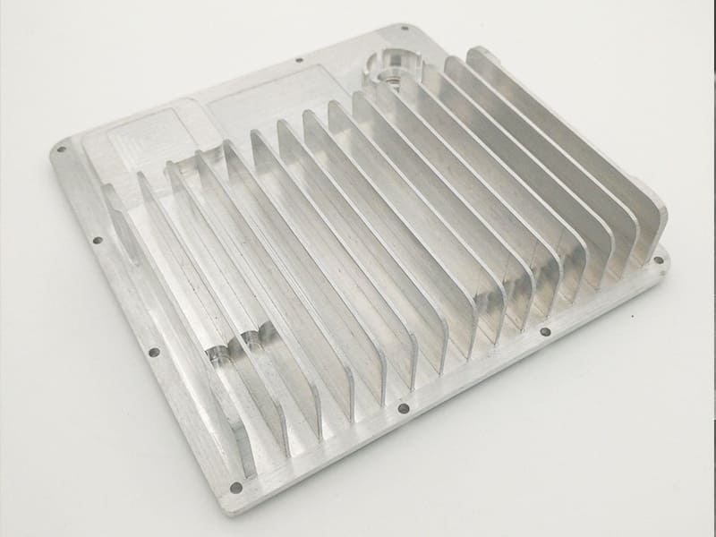
CNC Machined
CNC machining allows any fin geometry, any material, any feature arrangement, with no tooling investment. Appropriate for: prototypes and design iteration, complex geometries that cannot be extruded, low production volume, applications requiring high precision (tight flatness, controlled surface finish for thermal interface), aerospace and specialty applications.
CNC heat sinks in aluminum (6061-T6 or 6063-T6) or copper are the standard approach for prototype thermal validation before committing to extrusion tooling. From our manufacturing experience, a CNC-machined prototype heat sink allows the thermal designer to iterate fin spacing, base thickness, and geometry over 1–3 design cycles before final geometry is validated — this iteration is far less expensive before tooling than after.
Skived Fin
Skiving cuts thin fins directly from a solid metal block by controlled blade action, producing very thin fins (0.2–0.4 mm) at high fin density. Skived fins eliminate the bonding interface of brazed fin assemblies, maintaining full material conductivity from base to fin tips.
Appropriate for: high heat density applications where maximum surface area is required, IGBT modules, telecom base stations.
Bonded Fin (Brazed or Adhesive)
Bonded fin assemblies attach extruded or machined fin arrays to a base plate. They allow fin heights and aspect ratios that cannot be achieved by extrusion, and enable dissimilar material combinations (copper base, aluminum fins).
Appropriate for: maximum performance requirements, high-aspect-ratio fin arrays, hybrid material designs.
Pin Fin
Pin fin heat sinks use arrays of cylindrical or tapered pins rather than planar fins. Pin fins are less sensitive to airflow direction — they perform reasonably well with airflow from any direction, unlike planar fins that require aligned axial airflow.
Appropriate for: passive cooling applications, multi-directional airflow, compact packages where airflow direction is uncertain.
Application-Specific Design Guidance
| Application | Typical Power | Key Design Focus | Typical Structure |
|---|---|---|---|
| LED street lighting | 20–100W | Maximize passive area, vertical orientation | Radial or straight fin, aluminum extrusion |
| Motor drive (IGBT-based) | 50–200W | Thick base for heat spreading, forced air | Straight fin extruded or skived, 6–10 mm base |
| Power supply (enclosed) | 30–150W | Airflow path design, compact geometry | Straight fin, forced convection |
| EV traction inverter | 200–500W+ | Extreme heat density, size constraint | Copper base, skived/bonded aluminum fins, or liquid |
| CPU/GPU cooling | 65–250W | Fast heat spreading from small die | Heat pipe + copper contact plate, aluminum fins |
| Industrial controller | 20–100W | Reliability, dust resistance | Extruded aluminum, natural or slow forced convection |
| Telecom equipment | 100–300W | High airflow, front-to-back path | Straight fin, high-velocity forced air |
Common Design Mistakes and How to Avoid Them
| Mistake | Consequence | Correct Approach |
|---|---|---|
| Fin spacing too tight for fan capability | Airflow drops; fin area wasted | Match fin spacing to fan static pressure |
| Sizing at average power, not peak | Thermal failure at peak load | Size for peak + 20–30% safety margin |
| Using room-temperature ambient | System overheats at actual installed temperature | Use worst-case enclosure ambient |
| No airflow path verification | Hot air recirculates | Verify inlet-outlet separation; use CFD |
| Excessive thermal paste | Interface resistance increases | Apply 0.05–0.15 mm layer only |
| Thin base under high-flux source | Hot spot above source | Minimum 5–8 mm base for > 20 W/cm² |
| Switching to copper to fix overheating | Limited improvement if airflow is bottleneck | Fix airflow first; then consider material |
| Not testing in final enclosure | Lab performance does not match product | Test in representative enclosure with realistic airflow |
Key Takeaways
- Start with thermal resistance calculation, not fin geometry: determine the required R_sa before deciding on fin design, material, or structure.
- Airflow is the dominant performance variable: the convective coefficient in forced air (30–100 W/m²·K) is 5–10× that in natural convection (5–15 W/m²·K). Airflow design typically has more impact on performance than material or fin geometry.
- Size for worst-case ambient and peak power: laboratory testing at 25°C with ideal airflow is not the design condition. Industrial enclosures at 45–50°C ambient with partially restricted airflow is the design condition.
- Base thickness determines heat spreading quality: for heat flux above 20 W/cm², insufficient base thickness creates hot spots that no fin design improvement can address.
- Copper outperforms aluminum for heat spreading; aluminum dominates for cost, weight, and manufacturing at scale: hybrid designs (copper base, aluminum fins) capture both advantages.
- Extrusion is the standard for volume production; CNC machining is the correct choice for prototypes, complex geometry, and low-volume precision applications.
- For OEM procurement teams: heat sink specifications should include required thermal resistance (R_sa in °C/W at specified airflow velocity), mounting surface flatness (typically ≤ 0.05 mm for precision thermal interface), material grade, anodize specification (Type II for standard; Type III for wear resistance), and whether the component will be machined or extruded — each has different lead time and minimum order quantity implications.
Frequently Asked Questions
How do you calculate the thermal resistance required for a heat sink?
The required heat sink thermal resistance (R_sa) is calculated from: R_sa = (Tj_max − Ta) / Q − R_jc − R_TIM, where Tj_max is the maximum allowable junction temperature from the device datasheet, Ta is the worst-case ambient temperature in the actual installation environment (not laboratory conditions), Q is the peak power dissipation including transients, R_jc is the device’s junction-to-case thermal resistance, and R_TIM is the thermal interface material resistance. The result gives the maximum allowable heat sink thermal resistance — the heat sink must achieve this value or lower under the specified airflow conditions. Use a derated airflow assumption (70% of rated flow) to account for enclosure restrictions.
Why does my heat sink still overheat after upgrading to a larger size?
Overheating after adding a larger heat sink almost always indicates an airflow problem, not an insufficient heat sink. The most common causes are: hot air trapped inside a poorly ventilated enclosure (the heat sink is dissipating heat into air that is already hot from recirculation); airflow not actually passing through the fin channels (bypassing around the heat sink rather than through it); airflow direction misaligned with fin orientation; and thermal interface failure (excessive thermal paste, poor surface contact, or mounting pressure inconsistency). Before redesigning the heat sink, verify that cool ambient air reaches the fin channels, that heated air exits the enclosure without recirculating, and that the thermal interface is correctly applied.
What is the best fin spacing for a heat sink?
Optimal fin spacing depends on whether cooling is passive (natural convection) or active (forced air). For natural convection, 6–12 mm spacing is recommended — narrower spacing traps hot air between fins and reduces the temperature driving force for buoyancy-driven airflow. For forced air cooling, 2–4 mm is appropriate for typical small fans with static pressure of 1–5 mm H₂O. For high-static-pressure blowers or industrial fans, 1–2 mm may be effective. The critical design check: the fan must be able to maintain adequate airflow at the pressure drop produced by the chosen fin spacing. If fin spacing is reduced to increase surface area but the fan’s static pressure is insufficient to maintain flow, overall cooling performance decreases.
When should I use copper instead of aluminum for a heat sink?
Use copper when the heat source is highly concentrated (small contact area, high power density) and rapid lateral heat spreading is required to prevent hot spots. For a 100W IGBT module with a 20×20 mm contact footprint on a 60×60 mm base, copper’s higher conductivity (~390 vs ~200 W/m·K) reduces the hot-spot temperature by 10–20°C compared to aluminum. Copper is not the correct choice for improving convection efficiency — the convective heat transfer is limited by the air film boundary layer, not by the fin material. If overheating is caused by insufficient airflow rather than poor heat spreading, switching from aluminum to copper will produce minimal improvement. The hybrid design (copper base for spreading, aluminum fins for convection surface) captures the thermal advantage of copper where it matters while controlling weight and cost.
How does heat sink design change between natural and forced air convection?
Natural convection relies on buoyancy — hot air rising out of the fin channels draws cooler air in from below. For effective passive cooling: fins must be oriented vertically (aligned with the direction of rising hot air); fin spacing must be wide enough to allow buoyancy-driven flow without excessive friction (6–12 mm); the enclosure must have clear paths for cool air entry below and hot air exit above; and the heat sink surface area must be large enough to achieve the required heat dissipation at convective coefficients of only 5–15 W/m²·K. Forced air convection allows convective coefficients of 30–100+ W/m²·K, dramatically reducing the required fin area for the same heat load. The transition from natural to forced convection typically reduces required heat sink volume by 3–5× for the same thermal resistance target.
Written by the CMS engineering team with 15+ years of precision CNC machining experience producing custom aluminum and copper heat sinks for industrial electronics, power conversion, LED lighting, automotive, and telecommunications OEM applications. Technical references: Incropera & DeWitt, Fundamentals of Heat and Mass Transfer (Thermal Resistance Networks); JESD51-14 (Thermal Resistance Measurement of Electronic Devices); MIL-A-8625 (Anodic Coatings for Aluminum Heat Sinks); ASHRAE Thermal Guidelines for Data Communications Equipment.
Sourcing CNC Machined or Extruded Aluminum Heat Sinks?
At CMS, we machine custom aluminum and copper heat sinks in 6061-T6, 6063-T6, and copper C110 — from single-piece thermal prototypes for design validation to volume production. Every heat sink order includes DFM review for mounting surface flatness, fin geometry manufacturability, and anodizing compatibility.
[Request a thermal design review and custom heat sink machining quote →]


