
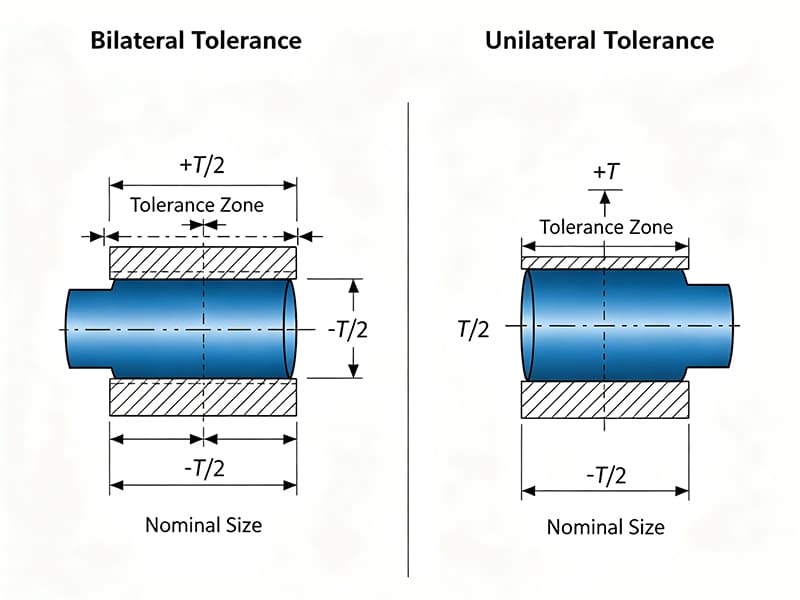
Quick Answer: Unilateral tolerance allows variation in one direction only (e.g., 10.00 +0.00/−0.05 mm — the dimension can only go undersized), protecting a critical boundary such as a maximum shaft diameter or minimum hole size. Bilateral tolerance distributes variation symmetrically around the nominal (e.g., 10.00 ±0.05 mm), which aligns with how CNC processes naturally behave and minimizes scrap in general machining. The decision is functional: use unilateral tolerance on any dimension where exceeding one limit causes assembly failure — shaft-into-bearing fits, sealing diameters, press-fit interfaces; use bilateral tolerance on non-functional dimensions where variation in either direction is acceptable. Most precision machined parts correctly use both: bilateral on general dimensions, unilateral on fit-critical features.
The Core Difference
The distinction between unilateral and bilateral tolerance is not a formatting preference — it determines which side of the nominal a part is allowed to vary toward, and therefore which assembly failure mode the tolerance specification protects against.
Bilateral tolerance: The tolerance zone is centered symmetrically around the nominal dimension. A bilateral specification of 10.00 ±0.05 mm means the actual dimension may be anywhere from 9.95 to 10.05 mm — equal variation above and below nominal is permitted.
Unilateral tolerance: The entire tolerance zone lies on one side of the nominal. A unilateral specification of 10.00 +0.00/−0.05 mm means the actual dimension may be anywhere from 9.95 to 10.00 mm — the dimension can be undersized but can never exceed 10.00 mm.
| Specification | Tolerance Zone | Lower Limit | Upper Limit | Variation Direction |
|---|---|---|---|---|
| 10.00 ±0.05 mm | 0.10 mm | 9.95 mm | 10.05 mm | Both (bilateral) |
| 10.00 +0.00/−0.05 mm | 0.05 mm | 9.95 mm | 10.00 mm | Undersize only (unilateral) |
| 10.00 +0.05/+0.00 mm | 0.05 mm | 10.00 mm | 10.05 mm | Oversize only (unilateral) |
The functional implication: a shaft specified at 10.00 ±0.05 mm could be machined to 10.05 mm, which may cause assembly interference with a 10.00 mm nominal bore. The same nominal shaft specified at 10.00 +0.00/−0.05 mm can never exceed 10.00 mm — the interference failure mode is eliminated by the tolerance structure itself.
Why Engineers Choose Bilateral Tolerance for Most Dimensions
Bilateral tolerance is the default specification for general machined dimensions not because it is simpler to write, but because it accurately reflects how CNC machining processes behave and how production variation distributes.
Process Centering
CNC machining processes — turning, milling, grinding — are programmed to a target dimension and tend to produce a distribution of actual dimensions centered near that target. When tool wear, thermal expansion, and vibration cause dimensional drift, the drift tends to be gradual and in both directions over time for a properly managed process. A bilateral tolerance accommodates this natural symmetry.
Statistical process control (SPC) works most effectively with bilateral tolerances: the process capability indices (Cp and Cpk) assume a normally distributed output centered on nominal. A process running to ±0.05 mm bilateral tolerance is straightforwardly assessed; a process running to a unilateral tolerance requires adjusting the nominal target and recalculating the effective mean, adding complexity to process monitoring.
Manufacturing Efficiency
A bilateral tolerance requires no deliberate process bias — the programmer targets nominal, and the natural variation of the process distributes on both sides. A unilateral tolerance, by contrast, requires the machinist or CNC programmer to intentionally target a dimension offset from nominal so that the process variation falls within the permitted zone on one side. This adds setup adjustment time and requires more frequent monitoring to detect when tool wear has shifted the process outside the intended zone.
Where Bilateral Tolerance Is Appropriate
Bilateral tolerance is the correct specification for any dimension where:
- The feature does not directly contact a mating part in a fit
- Small variation in either direction has no functional consequence
- The dimension defines the overall envelope or form of the part rather than a mating interface
- The feature is measured for quality control purposes rather than assembly verification
Typical bilateral-toleranced features on a precision CNC housing: overall length, width, and height; wall thickness; non-contact pocket dimensions; boss heights; chamfer depths; feature spacings that accumulate tolerance stack-up.
When Unilateral Tolerance Is Required
Unilateral tolerance is appropriate whenever one directional failure is acceptable and the other is not — when the part must not exceed one limit but has latitude in the other direction.
Shaft Diameters in Clearance Fits
A shaft specified for clearance fit into a bore must never exceed the maximum diameter that allows insertion. If the shaft is too small, clearance increases (acceptable for most clearance fits); if the shaft is too large, interference occurs and the assembly fails or requires forced entry that damages the bore.
The correct specification: shaft OD = 10.00 +0.00/−0.05 mm. The shaft is guaranteed to be at or below 10.00 mm. The only dimension that matters for assembly success (the maximum) is fully controlled.
A bilateral specification 10.00 ±0.05 mm on the same shaft permits a 10.05 mm shaft — which, combined with a 10.00 mm nominal bore at its lower tolerance limit, creates 0.05 mm of interference from the tolerance structure alone.
Precision Bore Diameters
A bore specified for shaft installation must never be smaller than the minimum diameter that clears the mating shaft. If the bore is oversized, running clearance increases (acceptable within design limits); if undersized, the shaft cannot be installed.
The correct specification: bore = 10.00 +0.05/+0.00 mm. The bore is guaranteed to be at or above 10.00 mm.
Press-Fit Interfaces
Press fits require controlled interference — the shaft diameter must be greater than the bore diameter by a specific amount to produce the required holding force. Both the minimum interference (insufficient retention) and the maximum interference (assembly damage) are functional failures, which means both limits matter. Press-fit specifications frequently use two unilateral tolerances: a unilateral tolerance on the shaft OD (holding minimum retention interference) and a unilateral tolerance on the bore ID (preventing excessive interference).
Sealing Surfaces
O-ring grooves and sealing diameters have critical dimensions that directly control seal compression. A groove diameter that is too large reduces O-ring compression below the sealing threshold; too small, and compression is excessive, accelerating O-ring wear. Both limits are functional, but the dominant failure mode (leakage from insufficient compression) is protected by a unilateral tolerance on the groove dimension that ensures compression is never below the minimum.
Thread and Gear Tooth Geometry
Thread pitch diameters for precision classes and gear tooth thickness specifications frequently use unilateral tolerances. For external threads (bolts, shafts), the pitch diameter must not exceed the maximum material condition to guarantee mating thread engagement. For gear teeth, tooth thickness must not exceed the MMC to prevent backlash-free binding in the mesh.
Maximum Material Condition and Unilateral Tolerance
Maximum Material Condition (MMC) is the condition where a feature contains the most material: for a shaft, MMC is the largest diameter; for a hole, MMC is the smallest diameter. MMC defines the worst-case condition for assembly clearance.
Unilateral tolerance and MMC naturally work together because unilateral tolerance ensures the feature never exceeds its MMC limit — it allows variation only in the direction that moves away from MMC.
For a shaft assembly:
- Shaft MMC = 10.00 mm (largest allowable shaft diameter)
- Unilateral tolerance: 10.00 +0.00/−0.05 mm → shaft is always at or below MMC
- Assembly clearance: guaranteed at all manufactured shaft dimensions
For a bore assembly:
- Hole MMC = 10.00 mm (smallest allowable bore diameter)
- Unilateral tolerance: 10.00 +0.05/+0.00 mm → bore is always at or above MMC
- Assembly clearance: guaranteed at all manufactured bore dimensions
A bilateral tolerance on the shaft (±0.05 mm) does not protect MMC — the shaft could be 10.05 mm, violating the MMC limit and causing assembly interference.
Tolerance Stack-Up: How Tolerance Type Affects Assembly Variation
In multi-component assemblies, dimensional variation from each part accumulates. This accumulation — tolerance stack-up — determines whether assemblies produced from correctly toleranced individual parts will fit together.
Bilateral Stack-Up
When bilateral tolerances are used on all mating dimensions, the worst-case stack-up is the arithmetic sum of all tolerance magnitudes. For three components each with ±0.05 mm bilateral tolerance:
Worst-case stack-up = 3 × 0.05 = ±0.15 mm total variation
The variation is symmetric — the assembly could be 0.15 mm larger or smaller than nominal.
Controlling Stack-Up with Unilateral Tolerance
Strategic application of unilateral tolerances can direct the stack-up in a predictable direction. If all tolerances on a linear assembly chain are specified as unilateral in the same direction, the worst-case result is a predictable one-sided error rather than a symmetric range — which can be designed around.
In practice, the most effective stack-up control approach combines:
- Bilateral tolerances on non-critical dimensions (allowing efficient machining)
- Unilateral tolerances on the one or two dimensions that directly govern assembly clearance (protecting the functional limits)
This mixed strategy provides most of the manufacturing efficiency of all-bilateral tolerancing with the assembly protection of functional unilateral control.
Example: Shaft + Housing Assembly
Three-component assembly: housing bore (nominal 30.00 mm), shaft OD (nominal 30.00 mm), thermal expansion allowance.
All bilateral design (problematic):
- Bore: 30.00 ±0.03 mm → range 29.97–30.03 mm
- Shaft: 30.00 ±0.02 mm → range 29.98–30.02 mm
- Worst case: bore at 29.97 mm, shaft at 30.02 mm → 0.05 mm interference — assembly failure
Mixed unilateral design (correct):
- Bore: 30.00 +0.05/+0.00 mm → always ≥ 30.00 mm
- Shaft: 30.00 +0.00/−0.03 mm → always ≤ 30.00 mm
- Worst case: bore at 30.00 mm, shaft at 30.00 mm → zero clearance (line-to-line) — assembly succeeds
CNC Machining Process Implications
Tool Wear and Directional Drift
In high-volume CNC production, tool wear introduces predictable directional drift: as a turning insert or end mill wears, external diameters trend smaller and internal diameters trend larger. This directional behavior makes unilateral tolerances in the direction of drift more achievable in practice than bilateral tolerances of the same total range.
For example, a bore machined with an end mill that wears over a production run: as the tool wears smaller, the bore diameter increases. A unilateral tolerance that allows only oversize (bore +0.04/+0.00 mm) aligns with this natural drift — the bore starts at nominal and drifts into the tolerance zone as the tool wears. A bilateral tolerance (±0.02 mm) on the same bore requires the process to start at nominal and maintain it within ±0.02 mm regardless of tool wear direction, requiring more frequent offset correction.
Inspection Strategy
The inspection approach differs between tolerance types:
For bilateral tolerances: measure the actual dimension and compare against the ±range from nominal. Process capability is assessed by comparing measured variation to the total tolerance band symmetrically.
For unilateral tolerances: inspection must specifically verify the critical limit. For a shaft with +0.00/−0.05 mm tolerance, the critical check is whether any part exceeds the maximum (nominal) dimension. Go/no-go gauges are particularly effective for unilateral tolerance inspection — the GO gauge verifies minimum material condition (must pass), and the NO-GO gauge verifies MMC (must not pass).
Application-Based Selection Guide
| Feature Type | Functional Requirement | Recommended Tolerance | Rationale |
|---|---|---|---|
| Shaft OD for clearance fit | Must not be oversized | Unilateral (+0.00/−x) | Prevents interference |
| Bore for shaft installation | Must not be undersized | Unilateral (+x/+0.00) | Ensures clearance |
| Press-fit shaft OD | Must maintain interference range | Unilateral (both limits critical) | Controls retention force |
| Bearing seat bore | H7 tolerance class | Unilateral per ISO 286-1 | Standard fit class |
| O-ring groove diameter | Must not be oversized | Unilateral | Protects seal compression |
| Housing outer envelope | Non-functional packaging | Bilateral | Machining efficiency |
| Wall thickness | Structural only | Bilateral | No fit requirement |
| General pocket dimensions | Non-contact | Bilateral | Process centering |
| Threaded hole position | Bolt pattern alignment | Bilateral (position), per ASME Y14.5 | Stack-up managed by GD&T |
| Gear tooth thickness | MMC at mesh point | Unilateral | Prevents backlash-free binding |
Common Selection Mistakes
Applying Bilateral Tolerance to Fit-Critical Dimensions
The most consequential tolerance mistake: specifying ±0.05 mm on a shaft that mates with a 0.00/+0.05 mm bore, without recognizing that worst-case (shaft at +0.05, bore at nominal) produces 0.05 mm interference. The error is not visible in individual part inspection — both parts pass their individual tolerances — but the assembly fails. The fix is to specify unilateral tolerance on either the shaft or the bore (or both) to eliminate the overlap.
Over-specifying Unilateral Tolerances Everywhere
The opposite error: applying unilateral tolerances to all features in an attempt to “control everything.” This forces the CNC process to intentionally target off-nominal dimensions for every feature, increasing setup time, making SPC more complex, and providing no functional benefit for non-critical dimensions. The process wastes control effort on features where it is not needed.
Specifying Tolerances Tighter Than Process Capability
Both tolerance types must be matched to achievable process capability. Standard CNC milling and turning: ±0.025–0.050 mm for general dimensions; ±0.010–0.025 mm for precision features; ±0.005 mm for high-precision work requiring controlled environment and specialized tooling. Specifying ±0.005 mm bilateral on a standard CNC milling operation, or +0.000/−0.005 mm unilateral, produces the same result: rejection rates that make production uneconomical.
Ignoring Stack-Up in Multi-Part Assemblies
Each dimension has variation, and variations accumulate across a mating assembly chain. An assembly designed with all bilateral tolerances and no stack-up analysis may have fit issues in production that appear only at the assembly stage — difficult and expensive to diagnose. The correct approach: complete a worst-case or RSS (root-sum-square) stack-up analysis before finalizing tolerances, then apply unilateral tolerances on the dimensions that govern assembly fit.
Key Takeaways
- Unilateral tolerance protects a specific limit — the dimension is guaranteed never to exceed (or go below) a critical boundary. This is the correct choice for shaft diameters in clearance fits, bore sizes for shaft installation, press-fit interfaces, and sealing surfaces.
- Bilateral tolerance matches natural CNC process behavior — machining processes center around nominal, and bilateral tolerances exploit this for manufacturing efficiency, process control, and SPC applicability. Correct for all non-functional, non-fit-critical dimensions.
- The practical approach uses both: bilateral on general dimensions (efficient machining), unilateral on fit-critical dimensions (assembly protection).
- Tolerance stack-up analysis should precede tolerance specification on any multi-part assembly: worst-case stack-up from all bilateral tolerances may produce interference that only appears at the assembly stage.
- Unilateral tolerance aligns with MMC: for any dimension where the MMC must never be violated for assembly to succeed, unilateral tolerance is the mechanically correct specification.
- CNC tool wear creates directional drift that can be exploited with unilateral tolerances: bores naturally drift oversize as tools wear, aligning with an oversize-only unilateral specification.
- For OEM procurement teams: drawings should specify both the tolerance type (bilateral ± or unilateral +/−) and the applicable fit class (ISO 286-1 for holes and shafts, ASME B4.2 for metric limits and fits) for all functional mating dimensions. A tolerance of “±0.05” on a bearing seat is insufficient — it does not protect the functional limit and will produce inconsistent bearing fits across production batches.
Frequently Asked Questions
What is the difference between unilateral and bilateral tolerance?
Bilateral tolerance distributes the allowable variation symmetrically around the nominal dimension — half above, half below — as in 10.00 ±0.05 mm (actual range: 9.95–10.05 mm). Unilateral tolerance places the entire tolerance zone on one side of the nominal — variation is only allowed in one direction — as in 10.00 +0.00/−0.05 mm (actual range: 9.95–10.00 mm) or 10.00 +0.05/+0.00 mm (actual range: 10.00–10.05 mm). The engineering consequence: bilateral tolerance cannot guarantee that a dimension will never exceed the nominal; unilateral tolerance can, making it the correct choice wherever exceeding one limit constitutes a functional failure.
When should unilateral tolerance be used?
Unilateral tolerance is required when one limit matters critically for assembly or function and the other does not. Primary applications: shaft outer diameters in clearance fits (the shaft must never be oversized — use +0.00/−x mm to prevent interference); bore diameters for shaft installation (the bore must never be undersized — use +x/+0.00 mm to ensure clearance); O-ring groove diameters (must not exceed the sealing limit); press-fit dimensions (where controlled interference is the functional requirement); and any feature where exceeding the Maximum Material Condition (MMC) would cause assembly failure.
Why is bilateral tolerance preferred for most CNC machining?
CNC machining processes are programmed to a target nominal and produce a distribution of actual dimensions centered near that target. Bilateral tolerance accommodates this naturally — the process runs at nominal, and variation distributes on both sides within the tolerance band without requiring deliberate process offset. This produces lower scrap rates, simpler SPC monitoring, and less frequent tool offset adjustment than unilateral tolerances, which require the machinist to intentionally target an off-nominal dimension so that process variation falls within the permitted zone on one side.
How does tolerance stack-up relate to unilateral vs bilateral tolerance choice?
Tolerance stack-up is the accumulation of dimensional variation across multiple mating parts in an assembly chain. All-bilateral tolerancing on a multi-part assembly produces the largest symmetric worst-case stack-up. Applying unilateral tolerances on the dimensions that directly govern assembly clearance can eliminate interference failures: if the shaft is specified unilateral to never exceed maximum size, and the bore is specified unilateral to never go below minimum size, the clearance between them is guaranteed at all manufactured dimensions within tolerance. The correct design practice is to perform worst-case stack-up analysis before finalizing tolerances, then use unilateral tolerances to protect the functional assembly limits while keeping bilateral tolerances on non-critical dimensions for manufacturing efficiency.
Does unilateral tolerance increase manufacturing cost?
For non-critical dimensions, yes — unilateral tolerance requires the process to intentionally target an off-nominal dimension and maintain that offset, which increases setup time and process monitoring frequency. For fit-critical dimensions, the cost comparison must include the cost of assembly failures: a bilateral tolerance that allows occasional interference requires expensive assembly-stage detection, rework, or scrapping of mated pairs. The additional machining control cost of unilateral tolerance on a critical shaft diameter is typically far less than the cost of field failures or assembly rejections from bilateral tolerance. The practical rule: use bilateral tolerances for manufacturing efficiency on all general dimensions, and accept the small additional control cost of unilateral tolerances on the specific dimensions where functional failure would result from exceeding one limit.
Written by the CMS engineering team with 15+ years of precision CNC machining experience producing shaft-bore assemblies, bearing housings, sealing components, and precision-fit mechanical parts for automotive, aerospace, medical, electronics, and industrial OEM manufacturing applications. Technical references: ASME Y14.5-2018 (Geometric Dimensioning and Tolerancing), ISO 286-1 (Limits and Fits — Bases of Tolerances, Deviations, and Fits), ASME B4.2 (Preferred Metric Limits and Fits), Machinery’s Handbook (Tolerances and Fits), Spotts & Shoup, Design of Machine Elements (Tolerance Analysis Methods).
Sourcing CNC Machined Precision Fit Components?
At CMS, we produce shafts, bores, bearing seats, press-fit inserts, and sealing surfaces with tolerance strategies specified to drawing requirements — unilateral for fit-critical features, bilateral for general dimensions. Every precision fit order includes DFM review for tolerance achievability, fit class verification, and stack-up analysis before production begins.
[Request a tolerance specification review and precision CNC machining quote →]


