
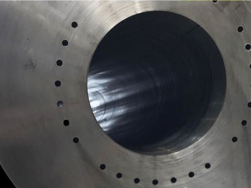
Quick Answer: Deep hole drilling is required when hole depth exceeds approximately 10× the hole diameter (L/D ≥ 10:1), where standard CNC drilling can no longer maintain straightness, control chip evacuation, or deliver adequate coolant to the cutting zone. The two principal industrial methods are gun drilling (Ø1–30 mm, L/D up to 100:1+, high straightness and surface finish) and BTA drilling (Ø20–500 mm+, higher material removal rate for large-diameter deep bores). Both use high-pressure through-tool or internal coolant (50–200 bar) and continuous chip evacuation mechanisms that conventional twist drills cannot provide. Gun drilling achieves straightness within 0.05–0.1 mm over 300–600 mm depth and surface finish of Ra ≤ 1.6 µm as-drilled. Deep hole drilling is essential for hydraulic cylinders, aerospace actuators, oil and gas downhole tools, firearms barrels, and mold cooling channels.
What Makes a Hole “Deep” — The L/D Ratio
In machining, hole depth is not measured in absolute millimeters — it is measured by the ratio of depth to diameter (L/D ratio). This ratio determines the engineering difficulty of producing the hole, because the fundamental challenges of deep hole drilling — tool deflection, chip evacuation, and thermal management — all scale with L/D ratio rather than with absolute depth.
A 100 mm deep hole at 20 mm diameter (L/D = 5:1) is entirely manageable with conventional CNC drilling. The same 100 mm depth at 5 mm diameter (L/D = 20:1) requires specialized deep hole drilling equipment. The diameter — not the depth — is the critical variable, because it determines tool stiffness, chip volume per revolution, and coolant delivery channel size simultaneously.
L/D Classification
| L/D Ratio | Classification | Typical Process |
|---|---|---|
| ≤ 5:1 | Standard hole | Conventional CNC drilling |
| 5:1–10:1 | Semi-deep hole | Enhanced peck drilling, through-coolant |
| 10:1–20:1 | Deep hole | Deep hole drilling or gun drilling |
| 20:1–50:1 | Very deep hole | Gun drilling or BTA drilling |
| 50:1–100:1+ | Ultra-deep hole | Dedicated gun drilling systems with steady rests |
The industry convention: L/D ≥ 10:1 officially designates a “deep hole” requiring specialized processes. Aerospace, oil and gas, and hydraulic component manufacturing routinely work with L/D ratios of 20:1 to 100:1.
Why Conventional Drilling Fails as L/D Increases
Tool deflection: A twist drill is a cantilevered beam. As hole depth increases, the unsupported tool length increases, and the drill deflects under cutting forces. A small angular error at the hole entry — 0.1° — produces 1.75 mm of lateral deviation over 1000 mm of depth. This drift is progressive and uncorrectable once it begins.
Chip evacuation breakdown: Chips must travel from the cutting edge all the way back up the flute to exit. At L/D 10:1, this distance is manageable. At L/D 20:1 or 30:1, chips pack into the flute, causing chip recutting (which degrades surface finish and accelerates tool wear), and eventually complete chip jamming that breaks the drill. This is the most common failure mode in deep hole conventional drilling.
Coolant inaccessibility: External flood coolant cannot penetrate effectively beyond approximately 5× diameter. Below this depth, the coolant flow rate and pressure reaching the cutting edge are insufficient to remove heat or flush chips, producing a hot, chip-packed cutting zone where tool failure is inevitable.
Vibration amplification: As overhang increases, natural frequency of the drill-spindle system decreases. At some overhang length, the cutting frequency coincides with the natural frequency, producing chatter — self-excited vibration that creates a wavy, rough bore surface and dramatically accelerates tool wear.
How Deep Hole Drilling Works: Process Engineering
Deep hole drilling systems overcome the limitations of conventional drilling through three integrated engineering solutions: guided cutting tools, high-pressure internal coolant, and controlled chip evacuation.
Gun Drilling
Gun drilling was originally developed for drilling rifle barrels — applications where bore straightness directly determines ballistic accuracy. The process uses a single-flute, solid carbide tool with:
Internal coolant channel: A precision-drilled channel runs through the tool body from shank to tip. High-pressure coolant (typically 50–150 bar, up to 200 bar for small diameters and hard materials) flows continuously through this channel and exits as a jet at the cutting edge. The coolant simultaneously cools the cutting zone, flushes chips, and provides hydraulic force to evacuate the swarf.
V-shaped flute: The single external flute provides a controlled path for chips and coolant to exit the hole. Chips ride in the V-groove back toward the drill entry as coolant flushes them out.
Guide pads: One or two hardened pads on the tool body, positioned circumferentially opposite the cutting edge, press against the bore wall as the tool advances. These pads accomplish two functions: they provide radial support that constrains the tool on its intended axis (preventing the drift that occurs in unsupported conventional drilling), and they burnish the bore wall surface as the tool passes, improving surface finish and roundness. The guide pads are the key feature that makes gun drilling a self-guiding process.
Chip formation and removal: The single cutting edge produces a chip that forms and is immediately directed into the V-flute by the coolant pressure. The chip geometry (controlled by edge angle) is designed to be short and rigid enough to travel back to the drill entry without packing.
Setup: Gun drilling typically requires the workpiece to be held and rotated while the drill is fed axially (workpiece-rotation mode, for better concentricity), or the drill can rotate while the workpiece is stationary (tool-rotation mode). Many specialized gun drilling machines support both configurations for different part geometries.
BTA Drilling (Boring and Trepanning Association)
BTA drilling addresses the requirements of large-diameter deep holes where gun drilling’s chip evacuation capacity (limited by the V-flute area) is inadequate for the chip volume produced at larger diameters.
Coolant flow direction reversal: Unlike gun drilling, where coolant flows through the tool and chips exit externally, BTA drilling uses the reverse arrangement. Coolant is delivered through the annular gap between the tool’s external diameter and the borehole wall, and chips are evacuated through the hollow bore of the tool and out through the connecting tube system.
Tool construction: A BTA drill head is a hollow cylinder with indexable cutting inserts at the front face. The hollow tool body connects to a chip collector and coolant supply system through the machine spindle.
Productivity: Because the chip evacuation cross-section (the tool bore area) is proportional to the square of the tool diameter, BTA drilling scales more efficiently to large diameters than gun drilling. At Ø50 mm and above, BTA drilling typically achieves 2–5× the material removal rate of gun drilling at equivalent depth.
Dimensional accuracy: BTA drilling provides high straightness and excellent roundness, though slightly below gun drilling at equivalent diameters, because the guide pad mechanism is different (pads in BTA heads typically contact only at the front face rather than over a significant axial length). For the application range where BTA is used (Ø20 mm and above), the achievable accuracy is entirely adequate for hydraulic cylinders, industrial shafts, and oil field components.
Ejector Drilling
Ejector drilling is a variant of BTA drilling for retrofitting onto conventional CNC machining centers. The coolant system uses a venturi effect to create internal chip evacuation without requiring the specialized machine head of BTA drilling. Ejector drilling is slower and somewhat less precise than dedicated BTA systems but enables deep hole capability on general-purpose CNC equipment for occasional deep hole requirements.
Gun Drilling vs BTA Drilling: Selection Guide
| Feature | Gun Drilling | BTA Drilling |
|---|---|---|
| Optimal diameter range | Ø1–30 mm | Ø20–500 mm+ |
| L/D capability | Up to 100:1+ | Up to 100:1+ |
| Straightness accuracy | Excellent | Good to very good |
| Surface finish (as-drilled) | Ra ≤ 1.6 µm typical | Ra 1.6–3.2 µm typical |
| Chip evacuation | External (V-flute) | Internal (through tool) |
| Coolant direction | Internal → out through flute | External → in through tool bore |
| Material removal rate | Moderate | High (scales with diameter) |
| Equipment required | Dedicated gun drill machine | Heavy-duty deep hole drilling machine |
| Best applications | Precision shafts, molds, medical, aerospace | Hydraulic cylinders, large shafts, oil field |
Selection rule: If the hole diameter is below approximately 20–25 mm and precision (straightness, surface finish) is the primary requirement, gun drilling is the correct process. If the hole diameter exceeds 20–25 mm and productivity or material removal rate is as important as accuracy, BTA drilling is more efficient. The overlap zone (Ø20–30 mm) is evaluated case by case based on tolerance and production volume.
Deep Hole Drilling vs Conventional CNC Drilling
| Factor | Conventional CNC Drilling | Deep Hole Drilling |
|---|---|---|
| Effective L/D range | ≤ 5:1 reliable; ≤ 10:1 with peck drilling | 10:1 to 100:1+ |
| Straightness | Degrades progressively with depth | Maintained by guide pad self-guiding |
| Coolant delivery | External flood (low pressure) | Internal high-pressure (50–200 bar) |
| Chip evacuation | External, gravity-dependent, unreliable at depth | Controlled, continuous, pressure-assisted |
| Surface finish achievable | Ra 1.6–6.3 µm | Ra ≤ 1.6 µm (gun drilling) |
| Diameter tolerance (deep holes) | ±0.1–0.3 mm (degrades with depth) | ±0.01–0.05 mm |
| Tool failure mode | Chip packing → catastrophic breakage | Gradual tool wear, predictable replacement |
| Equipment | Standard CNC machining center | Dedicated deep hole drilling system |
Accuracy and Surface Quality: How Deep Hole Drilling Achieves Them
Straightness Control Through Guide Pads
The guide pads riding against the bore wall are the mechanism that makes deep hole drilling self-correcting. Any lateral force that would otherwise deflect the tool is resisted by the reaction force from the pad contact, keeping the tool on its intended trajectory. This self-guiding property means that straightness error does not accumulate with depth — the tool actively corrects its axis with every revolution.
In production gun drilling, achievable straightness (deviation of the bore centerline from a true straight line over the full hole depth) is typically 0.05–0.3 mm per 1000 mm of depth, depending on material, diameter, and process conditions. For comparison, conventional peck drilling of a deep hole would produce drift of 0.5–2.0 mm per 1000 mm under comparable conditions.
Surface Finish Through Controlled Chip Evacuation and Burnishing
The internal surface finish of a deep hole is primarily determined by whether chips are evacuated cleanly without recutting. Recut chips — swarf that is carried forward by the tool and re-engaged with the cutting edge — produce scoring marks, longitudinal scratches, and poor roundness. In conventional deep drilling, chip recutting is essentially inevitable because chips cannot be consistently evacuated along the full flute length.
In gun drilling, chips are hydraulically swept away from the cutting edge as they form, delivered by the high-pressure coolant jet at the tip. The guide pads then burnish the resulting surface as the tool advances, closing surface micro-peaks and improving the finish. This combination of clean cutting and mechanical burnishing routinely produces Ra ≤ 1.6 µm as-drilled in standard materials (medium-carbon steel, aluminum, titanium alloys).
Process Metrics Reference
| Metric | Conventional CNC Drilling (L/D 10:1+) | Gun Drilling | BTA Drilling |
|---|---|---|---|
| Straightness (per 1000 mm) | 0.5–2.0 mm | 0.05–0.3 mm | 0.1–0.5 mm |
| Diameter tolerance | ±0.1–0.3 mm | ±0.01–0.05 mm | ±0.03–0.10 mm |
| Surface finish Ra | 3.2–12.5 µm | ≤ 1.6 µm | 1.6–3.2 µm |
| Roundness | Poor | Good | Good |
Applications That Require Deep Hole Drilling
Hydraulic Cylinders and Actuators
Hydraulic cylinder bores — the central bore of the cylinder body that the piston rod reciprocates in — require a combination of straightness (misalignment causes uneven seal wear and leakage), tight diameter tolerance (controls clearance that governs fluid bypass), and smooth surface finish (Ra ≤ 1.6 µm is standard before honing; Ra ≤ 0.4 µm after honing) that cannot be achieved with conventional drilling at the required L/D ratios.
A typical hydraulic cylinder bore for a mobile crane: Ø80 mm bore diameter × 2,000 mm depth (L/D = 25:1). This is a standard BTA drilling application. The bore is drilled to within 0.5 mm of final diameter, then finished with internal boring and honing to achieve the final sealing surface.
Aerospace Structural Components
Landing gear cylinders, flight actuator housings, and wing fold hinge pin bores are drilled in high-strength alloys (4340 steel, 300M steel, Ti-6Al-4V) where:
- Fatigue life is the governing design criterion — surface defects from chip recutting or conventional drilling instability are crack initiation sites
- Tight dimensional tolerances are required for bearing installation and seal fit
- Material is expensive and scrap is unacceptable
Gun drilling of aerospace components typically targets straightness of 0.05–0.1 mm per meter and surface finish of Ra ≤ 0.8 µm before subsequent honing. These requirements reflect both the functional requirements and the regulatory requirements of FAA/EASA-certificated aerospace manufacture.
Oil and Gas Downhole Tools
Drill collars, mud motor housings, and pressure vessels for downhole oil and gas tools are among the most demanding deep hole drilling applications:
- Large bore diameters (Ø50–300 mm) at depths of 500–3,000 mm
- Material is typically 4140 or 4145 modified high-strength alloy steel at 28–34 HRC
- Bore must be concentric and straight for pressure containment and fluid flow performance
- Production volume is moderate but part value is high (a single drill collar may cost $10,000–$50,000)
BTA drilling at high feed rates is standard for oil field component production. The chip evacuation efficiency of BTA at these diameters allows feed rates 2–4× higher than gun drilling would allow.
Firearms Barrels
Gun barrel drilling (the original application for which gun drilling is named) requires the combination of extreme straightness and fine surface finish that is the defining capability of the process. A rifle barrel of Ø7.62 mm × 600 mm (L/D ≈ 79:1) must be straight to within approximately 0.05 mm over its full length for acceptable accuracy; the bore surface must be Ra ≤ 0.8 µm before rifling to ensure uniform rifling engagement.
Injection Mold Cooling Channels
Injection mold cooling is accomplished through a network of drilled channels running through the mold body, close to the cavity surface, to extract heat rapidly and uniformly from the molded part. These channels are typically Ø6–16 mm at depths of 100–400 mm (L/D commonly 20:1–50:1), positioned with precision to achieve thermal uniformity at the cavity surface.
Poor positioning (from drift during conventional drilling) or poor surface quality (from chip recutting) both directly degrade mold cooling performance, increasing injection cycle time and part quality variation. Gun drilling of mold cooling channels provides the positioning accuracy and surface quality needed for predictable thermal performance.
Cost Structure of Deep Hole Drilling
Deep hole drilling costs more than conventional CNC drilling for the same hole diameter and depth, and the premium is justified by the process capabilities that make the hole actually functional. Understanding the cost drivers helps prioritize design decisions that reduce cost without sacrificing performance.
Primary Cost Drivers
Equipment: Dedicated gun drilling and BTA drilling machines are specialized, single-purpose equipment with capital costs of $200,000–$1,000,000+. This results in machine hourly rates typically 2–4× higher than standard CNC machining centers.
Tooling: Gun drills and BTA tool heads are precision-manufactured consumables. A Ø8 mm gun drill costs $80–$200 and produces approximately 50–200 holes (depending on material) before requiring resharpening or replacement. Resharpening extends tool life but requires specialized grinding equipment.
Cycle time: Deep hole drilling feed rates are lower than conventional drilling feed rates (to maintain chip formation geometry and avoid deflection). A Ø10 mm × 300 mm gun drilling operation might take 5–15 minutes of actual cutting time, depending on material and feed rate.
Coolant system: High-pressure coolant systems (pump, filtration, reservoir) represent a significant equipment investment and operating cost (pump power, filtration maintenance, coolant disposal).
Setup and qualification: Achieving consistent straightness and diameter requires careful setup — workpiece alignment, bushing or pilot hole preparation, coolant pressure and flow calibration, and initial test cuts. Setup time for a new deep hole drilling job is typically 2–4 hours for experienced operators.
Cost Reference
| Parameter | Approximate Cost Range |
|---|---|
| Ø6–12 mm gun drilling, medium alloy steel, 200–500 mm depth | $40–$150 per hole (production volume) |
| Ø20–50 mm BTA drilling, alloy steel, 500–1500 mm depth | $150–$600 per hole (production volume) |
| First-article setup and qualification | $500–$2,000 per new job |
The comparison that matters for procurement decision-making: the cost of deep hole drilling versus the cost of scrap parts, rework operations, and secondary honing from attempting the same holes with conventional CNC drilling. In our production experience running hydraulic cylinder components, failures during conventional deep drilling attempts — tool breakage requiring EDM extraction, hole drift requiring bore salvage or part scrap — produced total costs per failed part of $200–$800, far exceeding the cost differential of using the correct deep hole drilling process from the start.
DFM Guidelines for Deep Hole Drilling
Specify L/D Ratio Early in Design
The hole’s L/D ratio determines process selection, equipment requirements, and cost. A design change that reduces L/D from 25:1 to 15:1 (by changing a through-hole to a blind hole accessing from both ends, for example) may eliminate the need for specialized deep hole drilling and significantly reduce manufacturing cost. This trade-off analysis is only possible at the design stage.
Provide an Accurate Pilot Hole or Bushing for Entry Alignment
Gun drilling straightness depends critically on accurate alignment at hole entry. A small angular error at the start propagates to linear deviation over the hole depth. Standard practice: provide a precise pilot hole (2–3× diameter deep, within 0.02 mm of final position) or a hardened bushing at the entry to guide the drill accurately for the first few diameters before the guide pads engage the bore wall.
Allow Sufficient Stock for Tolerance Recovery
Deep hole drilling achieves high straightness and reasonable diameter accuracy, but not perfect. For precision assembly fits, allowances should be made for post-drilling finishing:
- Reaming: removes 0.05–0.2 mm and improves diameter tolerance to ±0.005–0.015 mm
- Boring: corrects diameter and minor positional error
- Honing: achieves Ra ≤ 0.4 µm and tight cylindricity for hydraulic sealing surfaces
Plan post-drilling stock accordingly: typically 0.1–0.3 mm on diameter for drilling-to-ream sequences; 0.05–0.15 mm on diameter for drilling-to-boring.
Avoid Cross-Holes and Interruptions in the Deep Hole Zone
Cross-holes, ports, or other features that intersect the deep hole in the drilling zone create dangerous interruptions for the drilling tool. When the drill crosses an internal void, the guide pads lose contact with the bore wall momentarily, the tool deflects, and hole straightness is disrupted. Design these features outside the deep hole zone wherever possible, or accept that drilling must stop and restart with careful process management at each interruption.
DFM Checklist for Deep Hole Drilling
| Design Decision | Recommendation |
|---|---|
| Define L/D ratio | Calculate from final diameter and depth; identify if ≥ 10:1 |
| Entry access | Provide flat, perpendicular surface at hole entry; specify pilot hole |
| Post-drilling stock | 0.1–0.3 mm diameter allowance for reaming or boring |
| Cross-hole intersections | Locate outside deep hole zone or accept process management requirement |
| Tolerance specification | Specify straightness and diameter tolerance separately; ±0.05 mm diameter is achievable; specify honing if tighter |
| Material specification | Include hardness range — HRC > 40 significantly increases cost and reduces achievable feed rate |
| Blind vs through hole | Through holes preferred for chip evacuation; blind holes require bottom-clearance depth specification |
Key Takeaways
- Deep hole drilling is required at L/D ≥ 10:1, where conventional CNC drilling can no longer maintain straightness, chip evacuation, or adequate coolant delivery.
- Gun drilling (Ø1–30 mm) provides the highest accuracy — straightness of 0.05–0.3 mm per meter, surface finish Ra ≤ 1.6 µm — through guide pad self-guiding and high-pressure through-tool coolant. Required for precision molds, aerospace components, medical devices, and firearms barrels.
- BTA drilling (Ø20 mm+) provides higher productivity for large-diameter deep bores through reverse-flow chip evacuation. Standard for hydraulic cylinders, industrial shafts, and oil field components.
- High-pressure internal coolant (50–200 bar) is the enabling technology — it simultaneously cools the cutting zone, evacuates chips, and hydraulically stabilizes the cutting process.
- Guide pads in gun drilling make the process self-guiding, actively correcting tool deviation on every revolution rather than allowing drift to accumulate.
- Cost premium is justified by yield and quality outcomes — attempting deep holes with conventional CNC drilling typically produces higher total cost than using the correct process, through scrap, rework, and secondary operations.
- For OEM procurement teams, deep hole drilling specifications should include: hole diameter and depth (for L/D calculation), required straightness (mm per meter or mm total), diameter tolerance class, surface finish (Ra before and after any secondary operations), material and hardness, and whether the hole is through or blind.
Frequently Asked Questions
What is considered a deep hole in machining?
A hole is considered “deep” when its depth exceeds approximately 10× its diameter (L/D ratio ≥ 10:1). At this ratio, conventional CNC drilling can no longer reliably maintain hole straightness, evacuate chips, or deliver adequate coolant to the cutting zone, and specialized deep hole drilling processes are required. Higher ratios — 20:1, 50:1, 100:1 — are routinely produced by gun drilling and BTA drilling for hydraulic cylinders, aerospace shafts, oil field components, and firearms barrels. The L/D ratio is a more useful design parameter than absolute depth because machining difficulty scales with the ratio, not with depth alone.
What is the difference between gun drilling and BTA drilling?
Gun drilling uses a solid single-flute tool with internal high-pressure coolant that flows to the cutting tip and returns through the V-shaped external flute, carrying chips back to the entry. It is optimized for small diameters (Ø1–30 mm), provides very high straightness accuracy (0.05–0.3 mm per meter), and achieves surface finish of Ra ≤ 1.6 µm. BTA drilling uses a hollow tool where coolant is supplied externally around the tool and chips are evacuated internally through the tool bore and connected tubing. It is optimized for large diameters (Ø20–500 mm+), provides high productivity through larger chip evacuation cross-section, and is the standard process for hydraulic cylinder bores, large industrial shafts, and oil field components.
How accurate is deep hole drilling?
Under production conditions, gun drilling achieves: hole straightness of 0.05–0.3 mm per 1,000 mm of depth; diameter tolerance of ±0.01–0.05 mm; roundness within 0.01–0.03 mm; and surface finish of Ra ≤ 1.6 µm as-drilled (Ra ≤ 0.4 µm achievable after honing). BTA drilling achieves: straightness of 0.1–0.5 mm per 1,000 mm; diameter tolerance of ±0.03–0.10 mm; surface finish of Ra 1.6–3.2 µm. These numbers are order-of-magnitude better than conventional deep CNC drilling, which typically produces straightness errors of 0.5–2.0 mm per 1,000 mm at equivalent L/D ratios.
Why does conventional CNC drilling fail on deep holes?
Three simultaneous failure mechanisms emerge as L/D increases beyond 10:1: tool deflection progressively worsens as unsupported overhang increases, causing hole drift that accumulates with depth; chips pack in the flute because they cannot travel back to the entry against the pressure drop over increasing depth, causing chip recutting that damages the surface and eventually jams the tool; and coolant cannot reach the cutting zone effectively because external flood coolant pressure is insufficient to penetrate along the full chip-filled flute to the cutting edge, resulting in thermal tool wear and potential workpiece surface damage. These three failures are interconnected — chip packing causes overheating, which causes tool wear, which causes more chip packing — producing a cascade that ends in tool breakage.
What industries use deep hole drilling?
The primary industrial applications are: hydraulic cylinders and actuators (Ø20–300 mm bores at L/D 20:1–50:1 for sealing surface quality and straightness); aerospace components (landing gear, actuator shafts, precision in high-strength alloys at L/D 20:1–60:1); oil and gas (drill collars, downhole tools at large diameters and high L/D ratios); firearms manufacturing (rifle and pistol barrels at L/D ratios up to 80:1+); injection molds (cooling channels at Ø6–16 mm at L/D 20:1–50:1 for thermal management); and precision mechanical components (fuel injector bodies, medical implant components, precision shafts in aerospace and defense applications).
Written by the CMS engineering team with 15+ years of precision CNC machining experience, including deep hole drilling coordination for hydraulic components, aerospace structural parts, and precision mold manufacturing. Technical references: SME Machining Handbook (Deep Hole Drilling), DIN 8589 (Metal Cutting Processes Classification), ISO 2768 (General Tolerances for Deep Hole Features), Sandvik Coromant Deep Hole Drilling Application Guide.
Sourcing Deep Hole Drilled Components or Coordinating Deep Hole Drilling With CNC Machining?
At CMS, we coordinate gun drilling and BTA drilling with CNC machining operations for hydraulic components, precision shafts, and mold cooling channels. Every deep hole specification is reviewed for L/D feasibility, straightness requirement achievability, post-drilling finishing sequence, and entry geometry before production begins.
[Request a DFM review and deep hole drilling quote →]


