
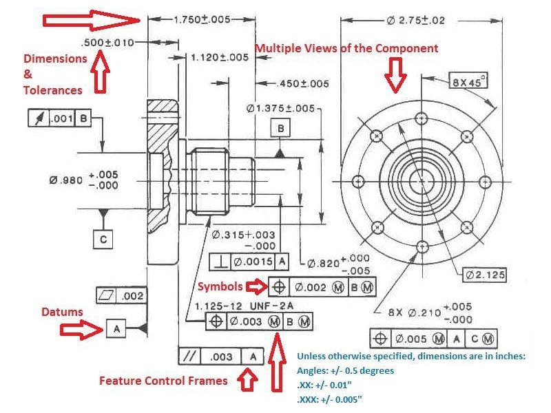
Quick Answer: Engineering tolerances define the allowable dimensional variation in a manufactured part — the acceptable range within which a part can still assemble, function, and meet performance requirements. Specified as a nominal dimension plus or minus an allowable deviation (e.g., 25.00 ±0.05 mm), tolerances control assembly fit, product reliability, and CNC machining cost. Tighter tolerances improve precision but increase machining time, inspection complexity, and scrap risk. The goal is matching tolerance to function — not specifying the tightest achievable value.
Why Engineering Tolerances Matter in Manufacturing
No machining process produces perfectly identical parts. CNC turning centers, milling machines, grinders, and injection molding presses all generate dimensional variation caused by tool wear, thermal expansion, machine vibration, and material inconsistency. Engineering tolerances exist to define how much variation is acceptable before a part fails to function correctly.
For OEM manufacturers sourcing precision CNC components, tolerances are among the most consequential specifications on a drawing. They determine whether parts assemble correctly across a production run, whether bearing fits will perform as designed, and — critically — how much a part will cost to produce. Tightening a tolerance from ±0.1 mm to ±0.02 mm on a machined bore might triple the machining time and require CMM inspection on every part, for a feature that may not functionally require that level of precision.
Properly designed tolerances balance three competing demands: functional performance, manufacturing capability, and production economics. Getting that balance right is one of the highest-value engineering activities in product development — and one of the most common sources of unnecessary cost when it goes wrong.
What Are Engineering Tolerances? Definition and Fundamentals
An engineering tolerance is the permissible limit of variation from a specified nominal dimension. It defines the acceptable range within which a manufactured dimension must fall to be considered conforming.
The standard representation is:
Nominal Dimension ± Allowable Deviation
For example, a shaft specified as 25.00 ±0.05 mm must measure between 24.95 mm and 25.05 mm after machining. Any part falling outside this range is non-conforming — regardless of how close it comes to the limit.
Why Exact Dimensions Are Not Achievable
Manufacturing variation is inevitable, produced by:
- Tool wear — cutting edges change geometry progressively, shifting dimensions as production runs
- Thermal expansion — spindles, fixtures, and workpieces expand as temperature rises during machining
- Machine vibration — dynamic forces during cutting create micro-displacement of the tool relative to the workpiece
- Material variation — hardness, grain structure, and residual stress vary within and between material batches
- Fixturing inconsistency — small variations in clamping force and workpiece seating change effective tool position
Tolerances acknowledge this reality and define the zone within which variation is acceptable for functional assembly and performance.
Nominal Dimension vs. Actual Dimension
The nominal dimension is the designer’s target — the theoretically ideal size. The actual dimension is what the machined part measures. Good tolerance design creates a range wide enough to be consistently achievable by the selected manufacturing process, while narrow enough to ensure reliable assembly and function.
In our production experience with precision CNC components, the most common drawing errors we encounter are tolerances that are either too tight for the specified process (creating unnecessary scrap and cost) or inconsistently applied — tight on non-functional features, loose on critical interfaces. Both create problems.
Types of Engineering Tolerances
Unilateral Tolerances
Unilateral tolerances allow variation in only one direction from the nominal dimension. A shaft specified as 25.00 +0.00/-0.05 mm can only be smaller than nominal — never larger. This is useful when one limit is functionally critical and the other is not.
When to use unilateral tolerances:
- Shaft-to-hole clearance fits where the shaft must not exceed nominal size
- Press-fit applications where interference must be guaranteed
- Any assembly where one limit creates interference or clearance failure and the other does not
Manufacturing advantage: Machinists can direct process drift toward the safe side of the tolerance window, improving yield without sacrificing function.
Bilateral Tolerances
Bilateral tolerances allow variation in both directions from nominal. 25.00 ±0.05 mm permits the dimension to be anywhere from 24.95 to 25.05 mm. This is the most common tolerance format in general CNC machining because it offers manufacturing flexibility — the process can drift in either direction without immediately producing non-conforming parts.
Best for: General machining, non-critical dimensions, features where symmetric variation is acceptable.
Limit Tolerances
Limit tolerances specify the upper and lower dimensional limits directly, without using ± notation. A bore specified as 25.01/24.98 mm defines exactly the acceptable range. This format eliminates ambiguity in inspection and is common in precision bearing fits and standardized hole systems.
Best for: Precision fits, bearing bores, any application where exact upper and lower limits must be clear to the inspector without arithmetic.
Geometric Tolerances (GD&T)
Geometric tolerances control shape, orientation, position, and runout — properties that dimensional tolerances alone cannot adequately define. A part may have every diameter within specification but still fail functionally if a bore is not concentric with the shaft centerline, or if a mounting surface is not flat enough for proper sealing.
GD&T (Geometric Dimensioning and Tolerancing) addresses these functional relationships through a standardized symbolic language defined by ASME Y14.5 (used widely in North America) and ISO GPS standards (used internationally). Key GD&T controls include:
| GD&T Control | What It Controls | Typical Application |
|---|---|---|
| Flatness | Surface deviation from a perfect plane | Sealing surfaces, machine bases |
| Circularity | Roundness of a cross-section | Bearing bores, shafts |
| Cylindricity | Combined roundness and straightness | Precision shafts, bores |
| Parallelism | Angular relationship between surfaces/axes | Rail systems, bearing housings |
| Perpendicularity | 90° relationship between features | Mounting faces, pillar bores |
| True position | Location of a feature relative to datums | Bolt hole patterns, functional bores |
| Concentricity | Axis-to-axis alignment | Rotating assemblies, eccentric features |
| Runout | Surface variation during rotation | Rotating shafts, spindles |
The practical power of GD&T is that it communicates functional intent rather than just dimensional limits. Specifying ±0.1 mm on a bolt hole diameter tells a machinist how big to make the hole, but true position ⌀0.2 mm tells them where the hole must be relative to the assembly datum — which is what actually determines whether the bolt goes in.
Tolerance Types Comparison
| Tolerance Type | Controls | Complexity | Best Application |
|---|---|---|---|
| Unilateral | Size (one direction) | Low | Press fits, critical single-limit features |
| Bilateral | Size (both directions) | Low | General machining, most features |
| Limit | Size (explicit upper/lower) | Low | Precision fits, bearing bores |
| GD&T | Geometry, position, orientation | Moderate–High | Precision assemblies, functional interfaces |
ISO 2768 and ASME Y14.5: Tolerance Standards That Drive CNC Production
ISO 2768: General Tolerances for CNC Machining
ISO 2768 is the most widely used international standard for general dimensional tolerances in CNC machining. It defines default tolerance classes that apply to all dimensions on a drawing where individual tolerances are not explicitly specified — eliminating the need to call out every dimension individually.
ISO 2768 defines four tolerance grades for linear dimensions:
| Grade | Code | Typical Linear Tolerance (for 30–120 mm) | Application |
|---|---|---|---|
| Fine | f | ±0.05 mm | Precision CNC machined parts |
| Medium | m | ±0.10 mm | General CNC machining (most common) |
| Coarse | c | ±0.20 mm | Sheet metal, general fabrication |
| Very coarse | v | ±0.50 mm | Welded assemblies, rough fabrication |
ISO 2768-m is the default specification for most general CNC machining. It balances precision with manufacturing efficiency — tight enough for most industrial assemblies, achievable by standard 3-axis CNC machining centers without special process controls.
When a drawing simply states “ISO 2768-m” without individual tolerance callouts on every dimension, the machinist and supplier understand the default tolerance applies to all unspecified dimensions. This dramatically simplifies drawings and reduces the engineering time needed to specify every non-critical feature.
ASME Y14.5: GD&T Standard for Functional Control
ASME Y14.5 is the primary GD&T standard used in the United States aerospace, automotive, and defense industries. It defines the symbolic language, rules, and interpretation methods for geometric tolerances on engineering drawings.
Key concepts defined by ASME Y14.5 include:
- Datums — reference points, axes, or planes from which measurements are taken
- Feature control frames — the symbolic boxes on drawings that specify tolerance type, value, and datum references
- Material condition modifiers (MMC, LMC, RFS) — rules that adjust tolerance zones based on actual feature size
- True position — the theoretically exact location of a feature relative to its datum structure
For OEM buyers reviewing supplier drawings or communicating specifications to CNC vendors, familiarity with ISO 2768 grades and ASME Y14.5 notation is practical knowledge that prevents misinterpretation and costly rework.
Engineering Fits: Clearance, Transition, and Interference
Engineering fits define how two mating components — typically a shaft and a hole — assemble relative to each other. The fit type is determined by the size relationship between the mating parts and directly affects assembly behavior, rotational performance, and mechanical stability.
Clearance Fit
In a clearance fit, the shaft is always smaller than the hole. The difference (clearance) allows free relative motion between the parts — rotation, sliding, or easy assembly and disassembly.
Clearance fit characteristics:
- Shaft is always smaller than hole
- Positive clearance under all tolerance conditions
- Allows rotation, sliding, or free assembly
- Clearance magnitude depends on specific tolerance grades selected
Applications: Plain bearings, rotating shafts in housings, sliding components, assemblies requiring frequent disassembly.
Critical design point: Too much clearance causes vibration, noise, and misalignment. Too little causes heat buildup and assembly difficulty. Bearing manufacturers publish specific clearance requirements for different speed and load conditions — these are the functional specs that drive tolerance selection, not arbitrary precision.
Transition Fit
A transition fit produces either slight clearance or slight interference depending on where within tolerance the mating parts actually measure. The tolerance zones of shaft and hole overlap, so the assembly outcome is statistically distributed between the two conditions.
Transition fit characteristics:
- May produce small clearance or small interference
- Requires controlled machining and inspection
- Provides better positional accuracy than clearance fits
- Allows disassembly without destructive force
Applications: Gear hubs, coupling flanges, locating pins, keyway bushings — anywhere accurate positioning matters but permanent assembly is not required.
Interference Fit
In an interference fit, the shaft is intentionally larger than the hole. Assembly requires force — either mechanical press fitting or thermal expansion (heating the housing or cooling the shaft to temporarily change dimensions). The resulting contact pressure creates strong mechanical retention without fasteners.
Interference fit characteristics:
- Shaft is larger than hole under all tolerance conditions
- Assembly requires force or thermal differential
- Creates high contact pressure between mating surfaces
- Provides excellent torque transmission and rigidity
Applications: Bearing outer rings in housings, gear hubs on shafts, permanent structural assemblies, press-fit pins and bushings.
Design caution: Excessive interference in brittle materials (cast iron, ceramics, hardened steel) can cause cracking during assembly. Interference must be calculated against material yield strength and assembly method capability.
Hole Basis vs. Shaft Basis System
The hole basis system holds the hole size constant and varies the shaft to achieve different fits. This is the standard approach in most CNC machining because standard drill, reamer, and boring tool diameters naturally produce consistent hole sizes — changing shaft size on a lathe is easier and cheaper than changing hole size.
The shaft basis system holds shaft diameter constant and varies the hole. This is used when standard bar stock shaft diameters are fixed by supply or other constraints.
For most OEM CNC machined components, hole basis system is the default. When specifying fits on engineering drawings for supplier production, this is the correct assumption unless there is a specific reason to use shaft basis.
Engineering Fits Summary
| Fit Type | Shaft vs. Hole | Assembly Method | Typical Application |
|---|---|---|---|
| Clearance | Shaft < Hole | Hand assembly | Bearings, rotating shafts, slides |
| Transition | Shaft ≈ Hole | Light press or hand | Gears, locating features, couplings |
| Interference | Shaft > Hole | Press fit or thermal | Permanent assemblies, high-torque joints |
GD&T in Depth: Datums, Feature Control Frames, and Key Controls
What Is a Datum?
A datum is a theoretically exact reference point, axis, or plane established by physical features on a part, used as the origin for all dimensional and geometric measurements. Datums simulate how parts actually sit, locate, and orient during assembly — making them the functional foundation of GD&T.
A datum reference frame typically uses three mutually perpendicular datums (primary, secondary, tertiary — labeled A, B, C) that progressively constrain the part’s degrees of freedom, mirroring how the part is fixtured during assembly or use.
Why datum selection is critical: Poor datum choice causes inspection results to vary between setups, even when the actual part geometry is identical. Datum features should be the same surfaces used for manufacturing setup and assembly location — not arbitrary convenient faces.
Feature Control Frame
The feature control frame is the rectangular box on an engineering drawing that specifies all GD&T requirements for a controlled feature. Reading left to right, it contains:
- Geometric characteristic symbol (e.g., ⌖ for true position, ⏥ for flatness)
- Tolerance value (e.g., ⌀0.2 mm — the diameter sign indicates a cylindrical tolerance zone)
- Material condition modifier (MMC, LMC, or RFS, when applicable)
- Datum references (primary, secondary, tertiary)
True Position
True position (⌖) is the most widely used GD&T control in precision manufacturing. It defines the theoretically exact location of a feature (typically a hole or boss axis) relative to its datums, and specifies a tolerance zone — usually a cylinder of diameter X — within which the actual feature axis must fall.
True position has two major advantages over coordinate dimensioning with ± tolerances:
More usable tolerance: A ± coordinate tolerance creates a square zone; true position creates a cylindrical zone. A cylindrical zone has 57% more area than the equivalent square zone — meaning the same functional requirement allows more manufacturing variation, reducing cost without sacrificing assembly performance.
Functional accuracy: True position directly reflects assembly function (does the bolt fit?), while coordinate tolerances reflect measurement convenience. GD&T communicates why a feature must be located precisely, not just where it should nominally be.
Flatness and Parallelism
Flatness controls how much a single surface may deviate from a theoretically perfect plane. It is independent of any datum — flatness is measured by the surface itself, not relative to anything else. Sealing surfaces on hydraulic manifolds, machine bases, and precision fixtures commonly carry flatness specifications because surface contact area directly affects sealing effectiveness and load distribution.
Parallelism controls the orientation of one feature relative to a datum surface or axis. It requires a datum reference and controls both the angle and straightness of the controlled feature relative to that reference. Bearing rails, slideways, and guide surfaces are typical parallelism applications — angular deviation creates uneven load distribution and accelerated wear.
Engineering Tolerances in CNC Machining: Realistic Capability
Understanding what CNC machining can reliably achieve — and where process limits lie — is essential for specifying workable tolerances.
Typical CNC Machining Tolerance Capability
| Process | Typical Achievable Tolerance | Surface Finish (Ra) | Notes |
|---|---|---|---|
| CNC milling | ±0.05–0.1 mm | 0.8–3.2 µm | Standard 3-axis, general features |
| CNC turning | ±0.01–0.05 mm | 0.4–1.6 µm | Concentric features, better than milling |
| Reaming | ±0.005–0.02 mm | 0.4–0.8 µm | Hole finishing, excellent roundness |
| Grinding | ±0.002–0.01 mm | 0.1–0.4 µm | High precision shafts, bores |
| Honing | ±0.001–0.005 mm | 0.05–0.2 µm | Cylinder bores, bearing surfaces |
| Lapping | ±0.001 mm or finer | < 0.05 µm | Ultra-precision, sealing surfaces |
What Limits CNC Precision
Several variables constrain achievable tolerance in production:
Machine rigidity: Chatter and deflection under cutting forces shift actual dimensions away from programmed values. High-rigidity machining centers handle tight tolerances better than general-purpose machines — but even the best machines have limits under aggressive conditions.
Tool deflection: Small-diameter end mills and long-reach tools flex under cutting forces, creating diameter variation and taper on machined features. In our production experience, a 6 mm end mill at 3× diameter depth of cut in alloy steel can deflect enough to produce 0.05 mm dimensional error — which is the entire tolerance budget on many precision features.
Thermal expansion: A typical steel workpiece expands approximately 12 µm per meter per °C. In a machining cycle that raises part temperature by 10°C, a 200 mm dimension changes by approximately 24 µm — significant when the tolerance is ±0.02 mm. Precision work requires temperature-stabilized environments and machined-in compensation.
Material behavior: Aluminum machines cleanly and holds dimensions well. Stainless steel work-hardens during cutting, causing springback and dimensional variation. Titanium’s low thermal conductivity concentrates heat at the cutting zone, affecting both surface quality and dimensional stability.
When to Specify Grinding Instead of Milling
For tolerances tighter than approximately ±0.01 mm, or surface finish requirements below Ra 0.4 µm, grinding is typically required rather than conventional CNC milling or turning. Grinding removes material with fine abrasives at high spindle speeds, producing dimensional and surface accuracy that carbide cutting tools cannot match. For OEM buyers specifying precision shafts, bearing bores, or sealing surfaces, understanding this process threshold helps set realistic tolerance expectations and avoid specifying tolerances that require process changes the quoted supplier may not have disclosed.
Tolerance Stack-Up Analysis: Why Individual Part Tolerances Are Not Enough
Tolerance stack-up occurs when dimensional variation from multiple components accumulates in an assembly, potentially causing functional failure even when every individual part is within specification.
How Stack-Up Happens
Consider an assembly with five components in a linear stack, each carrying a ±0.1 mm tolerance. In the worst case, all five parts could simultaneously be at their maximum (or minimum) limit — producing a total assembly variation of ±0.5 mm. Whether that assembly variation is acceptable depends entirely on the functional gap or clearance requirement.
Worst-Case Analysis
Worst-case analysis assumes the maximum possible stack — all components simultaneously at their extreme limits. This approach guarantees assembly success under any combination of manufactured part dimensions, but it may require tolerances tight enough to be uneconomical.
Best for: Safety-critical assemblies, low-volume production, applications where a single failure is unacceptable.
Limitation: Requires tighter individual part tolerances than may actually be necessary in production, where statistically it is very unlikely that all parts simultaneously fall at extreme limits.
Statistical Tolerance Analysis (RSS Method)
Statistical analysis uses root-sum-square (RSS) mathematics to calculate assembly variation based on the statistical distribution of individual part tolerances:
σ_assembly = √(σ₁² + σ₂² + σ₂² + … + σₙ²)
This approach reflects production reality more accurately: parts vary normally around their mean values, and the probability that all simultaneously reach their extremes is very low in volume production. Statistical methods allow looser individual tolerances for the same assembly functional reliability — reducing manufacturing cost without increasing assembly failure rate.
Best for: High-volume production, well-characterized manufacturing processes with known Cpk data.
Limitation: Requires process capability data (Cpk values) and accepts a small statistical probability of assembly failures, which must be evaluated against the consequence of failure.
How to Reduce Stack-Up Problems
- Apply GD&T datum-based design — consistent datums reduce positional variation accumulation across multiple parts in an assembly
- Reduce the number of components in critical stacks — fewer parts mean fewer tolerance contributions; consolidating components through design simplification directly reduces stack-up risk
- Tighten tolerances selectively — identify which component(s) in the stack contribute most variation and tighten those specifically, rather than tightening all parts equally
- Use adjustable interfaces — shims, set screws, and adjustable features allow assembly-stage compensation for accumulated tolerance variation
How Tolerances Affect Manufacturing Cost: The Economics of Precision
The relationship between tolerance and cost is non-linear. Standard tolerances (±0.1 mm range) are achievable in normal machining operations at normal speeds — cost impact is minimal. As tolerances tighten, machining time increases, inspection frequency rises, scrap rates grow, and eventually additional processes (grinding, honing) become necessary. The cost curve accelerates sharply at approximately ±0.01 mm and below.
Machining Time and Tolerance
Achieving tighter tolerances typically requires:
- Reduced cutting speeds and feed rates (less thermal and mechanical disturbance)
- Additional semi-finish and finish passes (incremental material removal)
- In-process gauging and compensation cycles (machine stops to measure, adjusts, then continues)
- Thermal stabilization between operations (waiting for temperatures to equilibrate)
A feature requiring ±0.05 mm might take 3 machining passes; the same feature at ±0.01 mm might require 6 passes plus an in-process measurement cycle — more than doubling cycle time for a single feature.
Inspection Cost
Verifying tight tolerances requires more capable and time-consuming equipment:
| Tolerance Range | Typical Inspection Method | Relative Inspection Time |
|---|---|---|
| ±0.1 mm and above | Digital calipers, simple gauges | Baseline |
| ±0.02–0.1 mm | Micrometers, air gauges | 2–3× |
| ±0.005–0.02 mm | CMM, precision gauging | 5–10× |
| ±0.001–0.005 mm | CMM with specialized probing | 10–20× |
| Below ±0.001 mm | Temperature-controlled CMM, laser interferometry | 20–50× |
For OEM buyers running high-volume production, CMM inspection time on every part at tight tolerance adds substantial cost — often more than the machining time itself. Specifying CMM inspection on non-functional features is a common over-specification that generates cost without quality benefit.
Scrap Rate and Tolerance Width
As the tolerance band narrows, the fraction of production that falls outside the acceptable range increases, because manufacturing process variation is fixed by machine capability — only the acceptable window changes. Doubling precision (halving tolerance width) typically more than doubles scrap rate, because the process distribution that was comfortably inside ±0.1 mm now clips the limits of ±0.05 mm more frequently.
The Over-Tolerancing Problem
In our shop floor experience reviewing customer drawings for DFM, over-tolerancing is the single most common and correctable cost problem. Engineers often apply the tightest tolerance they can reasonably imagine a part needing, rather than the tolerance functionally required. The result is machining cost 30–100% higher than necessary for the same functional outcome.
A practical approach: for every tight tolerance on a drawing, ask “what assembly or performance failure occurs if this dimension is 50% looser?” If the answer is “none,” loosen it.
Case Study: Fixing Assembly Problems Through GD&T Optimization
Background: A manufacturer of precision aluminum sensor housings was experiencing chronic assembly alignment problems on a multi-part assembly. Individual components passed dimensional inspection, but when assembled, hole patterns for sensor mounting frequently misaligned enough to require manual fitting — adding 8–12 minutes per assembly in labor and occasionally producing scrap assemblies that had to be disassembled and re-machined.
Initial tolerance strategy: The original drawings used bilateral dimensional tolerances (±0.1 mm on most features, ±0.05 mm on hole diameters) with no GD&T position control and no consistent datum strategy. Each component was measured from its own reference surfaces, which differed between parts.
Root cause: Without position tolerance controls, hole locations could simultaneously be at their worst-case combination across mating parts — up to 0.3 mm of cumulative misalignment was possible while every individual dimension remained technically conforming. Additionally, inconsistent datum usage between parts meant that machining setup references did not match assembly references, introducing systematic positional bias.
Engineering changes implemented:
| Element | Before | After |
|---|---|---|
| Position control | None (dimensional only) | True position ⌀0.15 mm |
| Datum structure | Inconsistent | Unified A-B-C datum system |
| Bearing bore specification | ±0.05 mm diameter | H7 limit tolerance + position control |
| Inspection method | Micrometers at machine | CMM with datum simulation |
| Fit type | Unspecified | H7/g6 clearance fit (hole basis) |
Results after implementation:
| Metric | Before | After |
|---|---|---|
| Assembly misalignment rate | ~35% of assemblies | < 3% of assemblies |
| Manual fitting time per assembly | 8–12 minutes | < 1 minute |
| CMM rejection rate (positional) | Not tracked | < 2% |
| Assembly scrap rate | ~8% | < 1% |
| Total assembly labor cost per unit | Baseline | Reduced ~28% |
Engineering lesson: The problem was not that tolerances were too loose — it was that the wrong type of tolerance was specified. Dimensional tolerances controlled feature size but said nothing about location. GD&T position tolerance, applied to a consistent datum structure, controlled what actually mattered for assembly: where the holes were relative to each other and to the mating component. For OEM buyers, this illustrates why asking your CNC supplier to review GD&T compliance — not just dimensional inspection — is worth the conversation on precision multi-part assemblies.
DFM Guidelines: Designing Engineering Tolerances for Manufacturability
Tolerance design is one of the highest-impact DFM (Design for Manufacturability) activities. Well-specified tolerances reduce machining cost, improve supplier consistency, and eliminate assembly problems before production begins. Poorly specified tolerances do the opposite — and the cost compounds through every production run.
Match Tolerance to Function
Apply tight tolerances only where functional performance actually requires them. Bearing bores, sealing surfaces, rotational interfaces, and precision locating features typically need tight tolerances. Cosmetic surfaces, non-contact edges, structural supports, and clearance features typically do not. Across a typical precision machined component, 15–25% of features are functionally critical; the remaining 75–85% can carry standard ISO 2768-m tolerances without affecting product performance.
Use Standard Fits
Standardized fits from the ISO fit system (H7/g6, H7/k6, H7/p6, etc.) are defined in every machining handbook, familiar to all CNC machinists worldwide, and achievable without special process development. Specifying custom tolerance combinations instead of standard fits creates confusion, requires more detailed inspection planning, and often produces no functional benefit.
Apply GD&T Selectively
GD&T is powerful but adds drawing complexity and inspection cost. Apply geometric controls only where geometry — not just size — determines functional performance. A sealing surface needs flatness. A bolt hole pattern needs true position. A non-functional boss face does not need either.
Avoid Cascading Tight Tolerances
Specifying tight tolerances on multiple features in a tolerance stack compounds the cost and manufacturing difficulty. Identify the one or two dimensions that are actually controlling assembly fit, apply precision there, and allow standard tolerances elsewhere.
DFM Tolerance Checklist
| Design Check | Action |
|---|---|
| Is this tolerance functionally required? | If not, loosen to ISO 2768-m |
| Can a standard fit replace a custom tolerance? | Use H7/g6, H7/k6, etc. |
| Are datums consistent with manufacturing setup? | Align drawing datums with fixturing datums |
| Has tolerance stack-up been analyzed? | Run worst-case or RSS analysis on critical stacks |
| Does the specified tolerance match process capability? | Verify supplier Cpk data for critical features |
| Is GD&T applied only where geometry matters? | Remove GD&T from non-functional features |
Inspection Methods for Engineering Tolerances
Selecting the right inspection method is as important as specifying the right tolerance. The inspection method must be capable of measuring to the required precision — using a digital caliper to inspect a ±0.005 mm tolerance feature is physically meaningless.
Calipers and Micrometers
Digital calipers (resolution 0.01 mm, measurement uncertainty ±0.02–0.05 mm) are appropriate for general dimensional inspection at tolerances of ±0.1 mm and above. They are fast, portable, and suitable for shop-floor use on non-critical features.
Micrometers (resolution 0.001 mm, measurement uncertainty ±0.002–0.005 mm) are suitable for tolerances down to approximately ±0.01 mm on external dimensions. They are the standard tool for shaft diameter inspection in precision CNC production.
Coordinate Measuring Machines (CMM)
CMMs use a precision probing system in 3D space to measure geometry, position, flatness, and other GD&T characteristics. Modern CMMs achieve measurement uncertainty of ±0.001–0.003 mm with appropriate probing and environmental controls.
CMM inspection is essential for true position, profile, flatness, and parallelism tolerances — GD&T controls that simple hand tools cannot measure. For OEM buyers receiving precision components, CMM inspection reports with datum-referenced measurements are the appropriate quality documentation for critical features.
Go/No-Go Gauges
Go/No-Go gauges provide fast, unambiguous pass/fail verification of dimensional tolerances without measuring the actual value. The “Go” end of the gauge must enter the feature (verifying minimum material condition); the “No-Go” end must not enter (verifying maximum material condition).
Go/No-Go gauges are highly efficient for high-volume production inspection of standardized features — bore diameters, shaft diameters, thread fits — where 100% inspection is required but CMM throughput is insufficient. Their limitation is that they provide no dimensional data for statistical process control.
Optical and Non-Contact Systems
Optical comparators, vision systems, and laser scanning systems measure dimensions without physical contact, making them ideal for fragile features, small geometry, and complex surface profiles. Modern optical CMMs achieve accuracies comparable to contact CMMs for surface and position measurements, with higher speed for suitable geometries.
Applications by Industry
Automotive
Modern vehicle assemblies require tight tolerance control on thousands of interacting components — but cost pressure at production volumes of hundreds of thousands per year makes tolerance optimization critical. Engine components (bores, crankshafts, valve seats), transmission gears, and bearing fits carry tight functional tolerances. Structural brackets, housings, and non-critical supports use standard tolerances. Statistical process control (SPC) monitors key characteristics in real time, catching process drift before it generates scrap.
Aerospace
Aerospace tolerance requirements are among the most demanding in manufacturing. Landing gear components, structural fittings, control system parts, and engine components often require tolerances of ±0.005–0.025 mm with full GD&T position and profile control. All characteristics require documented inspection with CMM data and traceability to calibration standards. According to AS9100 quality system requirements, aerospace suppliers must demonstrate process capability (Cpk ≥ 1.33) on critical characteristics — which means not just meeting tolerance but meeting it consistently across the distribution of production.
Medical Devices
Surgical instruments, implants, and diagnostic equipment require precision tolerances for functional and regulatory compliance reasons. Implant bearing surfaces, for example, may carry surface finish specifications of Ra ≤ 0.05 µm and diameter tolerances of ±0.005 mm or tighter — requiring grinding and lapping operations and 100% CMM inspection. ISO 13485 quality system requirements mandate documented process validation and traceability for all critical dimensions on medical devices.
Precision Tooling
Injection molds, stamping dies, and cutting tool bodies require precision tolerances because tooling inaccuracies translate directly to dimensional variation in every produced part. A mold cavity that is 0.05 mm oversized produces parts that are 0.05 mm oversized — multiplied by every shot across the tool’s life. For OEM buyers specifying tooling for plastic or stamped metal components, tooling tolerance is the upstream investment that determines downstream part quality.
Key Takeaways
- Engineering tolerances define the acceptable variation range — the zone within which a manufactured dimension must fall for a part to be functionally conforming.
- Four main tolerance types — unilateral, bilateral, limit, and GD&T — serve different functional and manufacturing purposes. GD&T controls geometry, not just size.
- ISO 2768-m is the standard default for general CNC machining; ASME Y14.5 provides GD&T rules for precision functional control.
- Engineering fits (clearance, transition, interference) define assembly behavior between mating components — hole basis system is the standard for most CNC machined assemblies.
- Tolerance stack-up can cause assembly failure even when individual parts are conforming — always analyze cumulative variation for multi-part assemblies.
- Tighter tolerances cost exponentially more — machining time, inspection complexity, and scrap rate all increase non-linearly as tolerance bands narrow.
- Over-tolerancing is the most common DFM mistake — apply tight tolerances only where functional performance requires them, and use standard ISO 2768-m elsewhere.
- For OEM buyers, reviewing GD&T compliance and requesting CMM inspection reports on critical features is the correct approach for precision multi-part assemblies.
Frequently Asked Questions
What are engineering tolerances and why are they important?
Engineering tolerances define the permissible dimensional variation in a manufactured part — the acceptable range between minimum and maximum dimensions that still allows correct assembly and function. They exist because no manufacturing process can produce perfectly identical parts: tool wear, thermal expansion, vibration, and material variation all create dimensional deviation. Without tolerances, there is no objective standard for accepting or rejecting parts. They directly affect assembly quality, product reliability, CNC machining cost, and interchangeability — making them one of the most consequential specifications on any engineering drawing.
What is the difference between unilateral and bilateral tolerances?
Unilateral tolerances allow variation in only one direction from nominal — for example, 25.00 +0.00/-0.05 mm, where the part can only be smaller than the nominal value. Bilateral tolerances allow variation in both directions — 25.00 ±0.05 mm, where the part can be larger or smaller. Unilateral tolerances are useful when one limit is functionally critical and the other is not, such as shaft fits where the shaft must not exceed nominal size. Bilateral tolerances are more common in general CNC machining because they give manufacturing flexibility to accommodate process drift in either direction without immediately producing non-conforming parts.
What is GD&T and how does it differ from standard dimensional tolerances?
GD&T (Geometric Dimensioning and Tolerancing) is a symbolic engineering language — standardized by ASME Y14.5 in North America — that controls the shape, orientation, position, and runout of manufactured features. Standard dimensional tolerances control only size variation (how big a feature is). GD&T controls functional geometry — whether a surface is flat, whether a hole is in the right location relative to an assembly datum, whether a shaft is concentric with its bearing bore. This distinction is critical because a part can have every diameter within dimensional specification yet still fail functionally if features are misaligned. GD&T is widely used in aerospace, automotive, and medical device manufacturing where functional assembly performance must be explicitly controlled.
How tight can CNC machining tolerances be?
Standard 3-axis CNC milling achieves ±0.05–0.1 mm under normal conditions. CNC turning achieves ±0.01–0.05 mm on concentric features. Reaming brings bore tolerances to ±0.005–0.02 mm. Grinding achieves ±0.002–0.01 mm. Honing and lapping reach ±0.001 mm and below for ultra-precision applications. Below approximately ±0.01 mm, conventional CNC machining is generally insufficient and grinding or honing is required. Very tight tolerances also require temperature-controlled environments, since thermal expansion of the workpiece itself causes dimensional drift at these precision levels. Specifying tighter tolerances than the manufacturing process can reliably achieve increases cost dramatically without improving yield.
What are clearance, transition, and interference fits?
These three fit types define how a shaft and hole assemble relative to each other. A clearance fit always has the shaft smaller than the hole — producing positive gap that allows rotation, sliding, or free assembly. A transition fit has overlapping tolerance zones, producing either slight clearance or slight interference depending on actual measured dimensions — used where accurate positioning matters but permanent assembly is not needed. An interference fit always has the shaft larger than the hole — requiring press-fit force or thermal assembly, producing high contact pressure and strong mechanical retention. The correct fit type depends on the assembly function: clearance for bearings and rotating parts, transition for locating features, interference for permanent structural joints.
How does tolerance stack-up affect assembly quality?
Tolerance stack-up occurs when dimensional variation from multiple components accumulates in an assembly, potentially causing functional problems even when every individual part is within its specified tolerance. In a linear assembly of five components each carrying ±0.1 mm tolerance, the worst-case cumulative variation is ±0.5 mm — five times any single part’s allowance. If the assembly clearance requires less than 0.5 mm variation to function, assembly failures will occur despite every part being individually conforming. Stack-up analysis — using worst-case methods for safety-critical applications or RSS statistical methods for high-volume production — identifies which components drive assembly variation and where tolerance tightening or design simplification will most effectively reduce failure risk.
Why does tolerance affect CNC machining cost so significantly?
Achieving tighter tolerances requires slower machining (to reduce thermal and mechanical disturbance), additional machining passes (semi-finish and finish), in-process gauging and compensation cycles, and often entirely different processes (grinding instead of milling). Inspection time increases non-linearly — verifying ±0.005 mm tolerances requires CMM inspection, which takes 5–20× longer than simple gauge or micrometer checks. Scrap rate increases as the acceptable dimensional window narrows relative to the process distribution. For OEM buyers, these costs are reflected in machined part pricing: a component with unnecessary tight tolerances may cost 50–100% more than functionally equivalent parts with properly matched tolerances. Reviewing tolerance specifications with your CNC supplier before finalizing drawings is a high-value step for any precision component.
What inspection method is appropriate for different tolerance levels?
The inspection method must match the required measurement precision. Digital calipers (±0.02–0.05 mm uncertainty) are appropriate for tolerances of ±0.1 mm and above. Micrometers (±0.002–0.005 mm) suit tolerances down to approximately ±0.01 mm on external dimensions. Coordinate measuring machines — CMMs — are required for GD&T geometric controls (true position, flatness, parallelism) and for dimensional tolerances below ±0.01 mm. Go/No-Go gauges provide fast 100% pass/fail verification in high-volume production without quantitative measurement. For OEM buyers receiving precision components, requesting CMM inspection reports with datum-referenced measurements for critical GD&T features is the appropriate quality standard — simple dimensional reports without position data are insufficient for complex precision assemblies.
Written by the CMS engineering team with 15+ years of precision CNC machining experience in engineering tolerance optimization, GD&T implementation, and precision assembly for aerospace, automotive, and industrial OEM applications. Technical references: ASME Y14.5-2018 (Dimensioning and Tolerancing), ISO 2768 (General Tolerances), ISO 286 (Limits and Fits), AS9100 Rev D (Aerospace Quality Management).
Need Precision CNC Components With the Right Tolerances — Not Just Tight Ones?
At CMS, we review engineering tolerance specifications as part of every DFM analysis, flag over-toleranced features that are adding cost without functional benefit, and suggest GD&T improvements that improve assembly reliability without increasing machining complexity. Whether you’re sourcing single components or managing a multi-part precision assembly, our engineering team brings the tolerance expertise your project needs.
[Request a DFM tolerance review and machining quote →]


