
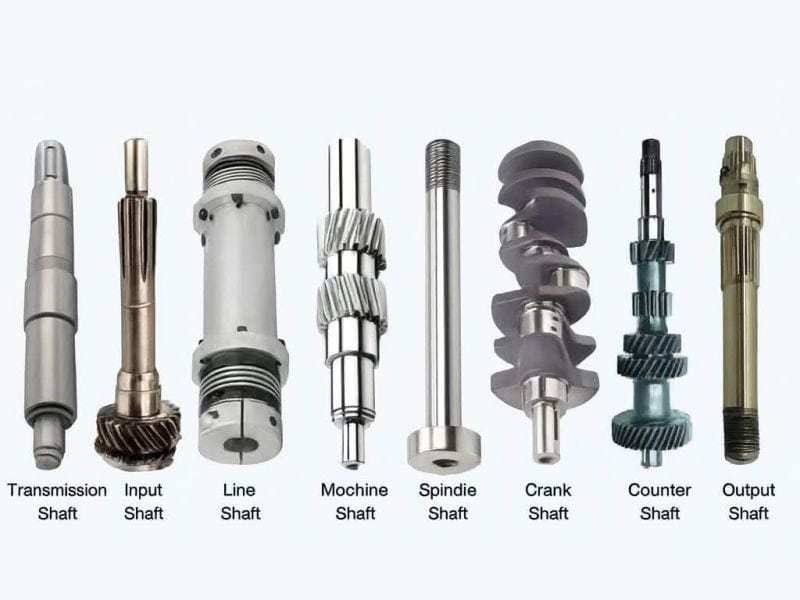
A shaft is the component that makes rotation useful. Strip away the housing, the gears, the bearings — and what remains is the shaft, quietly carrying torque from where power is generated to where it’s needed. Every electric motor, gearbox, pump, and drivetrain depends on one. Understanding what a shaft is used for goes well beyond describing a cylindrical rod; it means understanding how machines actually transmit power under load, cycle after cycle, for years of service.
For designers and engineers, shafts define load paths, stiffness, and fatigue life in rotating assemblies. For procurement teams, material grade, heat treatment, and manufacturing method directly control cost, lead time, and reliability. This article covers the full picture: shaft functions in real machines, shaft types and their applications, material selection logic, manufacturing processes, and tolerance requirements for custom shaft specifications.
Engineering Definition: What Is a Shaft?
In mechanical engineering, a shaft is a rotating machine element whose primary function is transmitting torque and mechanical power between components. What distinguishes a shaft from other cylindrical parts is function, not shape. If a rotating component carries torque and drives something else, it’s a shaft.
That said, several related terms get used interchangeably in non-technical contexts. In engineering, the distinctions matter:
| Component | Rotates | Transmits Torque | Typical Role |
|---|---|---|---|
| Shaft | Yes | Yes | Motor shafts, gearbox shafts, pump shafts |
| Axle | May or may not | No | Wheel supports, load-bearing members |
| Rod | No | No | Tie rods, linkages, structural supports |
| Spindle | Yes | Yes (light–moderate) | CNC machine tools, precision drives |
An axle supports loads — even if it rotates, it doesn’t transmit torque to a driven component. A rod is non-rotating and structural. A spindle is a specialized shaft optimized for precision, speed, and low runout rather than high torque capacity. Confusing these roles during design leads to incorrect material selection, wrong tolerance callouts, and performance problems that are expensive to fix after the fact.
Unlike static structural members, shafts operate under combined loading: torsion from transmitted torque, bending from gear mesh forces or belt tension, and cyclic stresses from continuous rotation. Shaft design is therefore governed by fatigue endurance, stiffness, and vibration behavior — not just static load capacity.
What Is a Shaft Used For in Real Machines?
The answer spans three distinct functions, and most shafts perform all three simultaneously.
Power and Torque Transmission
The core function is straightforward: carry power from a source to a load. A typical industrial power chain looks like this — electric motor output shaft → gearbox input shaft → gearbox output shaft → driven equipment. Each shaft in that chain transmits torque while absorbing the torsional fluctuations that come with real operating conditions: startup surges, load spikes, braking events.
Torsional stiffness matters here as much as strength. A shaft that deflects significantly under torque introduces phase error between the driver and driven equipment. In precision motion systems — servo-driven axes, coordinated multi-spindle machines — that phase error translates directly into positioning inaccuracy or synchronization faults.
Supporting and Locating Rotating Components
Shafts also function as the structural backbone for the components mounted on them. Gears, pulleys, sprockets, couplings, and impellers are all located by the shaft — held in position by keys, splines, press fits, or locating shoulders. Bearings then support the shaft itself, constraining deflection and maintaining alignment throughout the load spectrum.
In this role, bending stiffness is as critical as torque capacity. A gear shaft that deflects under load shifts the gear mesh contact pattern, increasing noise, accelerating wear, and reducing gear life. Bearing span, shaft diameter, and material stiffness all feed directly into how well a shaft keeps components where they belong under operating loads.
Motion Control and Synchronization
Beyond raw power transmission, shafts synchronize machine elements. Speed ratios between connected shafts determine gear ratios and throughput rates. Angular phase relationships govern timing in multi-station machines. In packaging equipment, printing presses, and automated assembly lines, small phase errors cause product defects, registration failures, or jams — which is why shaft stiffness, coupling selection, and torsional resonance all appear in the design checklist for these applications.
Main Shaft Types and Their Engineering Applications
Shaft classification is based on function and load condition, not geometry. The same material and diameter can serve very different roles depending on how loads are applied and what the shaft connects.
Transmission Shafts
These shafts transfer power between separated machine elements. Drive shafts, propeller shafts, and cardan shafts all belong here. Primary loading is torsion, with secondary bending from angular misalignment or intermediate support points. Applications span automotive drivetrains, industrial gearboxes, and conveyor systems. Design priority: torque capacity, fatigue strength, and tolerance of minor misalignment without excessive bending stress.
Machine Shafts
Crankshafts, camshafts, motor shafts, and pump shafts are machine-specific components that are integral to how a particular machine operates. These shafts carry complex combined loads — torsion, bending, and axial thrust often acting simultaneously — and they typically have strict requirements for surface finish, balance, heat treatment, and dimensional accuracy. A crankshaft in a diesel engine, for example, must withstand peak cylinder pressures every firing cycle for millions of cycles at operating temperature. That’s a fatigue problem, not a static strength problem.
Line Shafts and Counter Shafts
Historically used to distribute power across factory floors from a single prime mover, line shafts are less common in modern facilities but still appear in legacy industrial systems and some heavy process equipment. Counter shafts serve as intermediate elements for speed change or direction change within gear trains. Primary engineering concern: bending over long unsupported spans, and torsional resonance when shaft length-to-diameter ratios become large.
Spindles
Spindles are precision shafts optimized for accuracy, stiffness, and speed rather than torque. CNC machining center spindles operate at 8,000–30,000 RPM with runout requirements measured in microns. Bearing preload, thermal stability, and dynamic balance dominate spindle design. These components share the shaft’s basic function — rotating and transmitting torque — but their design is governed by accuracy requirements that exceed what’s needed in conventional power transmission.
Solid vs Hollow Shafts
Solid shafts are simpler to manufacture and offer high stiffness for a given outer diameter. They’re the standard choice for small to medium power systems where weight isn’t a constraint.
Hollow shafts distribute material toward the outer radius, where it contributes most to torsional and bending stiffness. For the same mass, a hollow shaft achieves meaningfully higher section modulus than a solid one. A hollow shaft with outer diameter D and inner diameter d = 0.6D, for instance, retains about 87% of the solid shaft’s torsional stiffness at only 64% of the weight. In automotive driveshafts, aerospace actuators, and high-speed machine tool spindles, that weight reduction directly reduces rotational inertia and bearing loads.
| Shaft Type | Primary Function | Governing Loads | Common Applications |
|---|---|---|---|
| Transmission shaft | Power transfer | Torsion + bending | Drivetrains, conveyors |
| Machine shaft | Machine-specific operation | Torsion + cyclic loads | Engines, motors, pumps |
| Line shaft | Power distribution | Bending-dominant | Factory systems |
| Counter shaft | Speed/direction change | Torsion + bending | Gear trains |
| Spindle | Precision rotation | High speed, low runout | CNC machine tools |
| Hollow shaft | Efficient torque transfer | Torsion | Automotive, aerospace |
Loads and Stress: What a Shaft Actually Experiences in Service
Most shaft failures aren’t caused by single-event overload. They’re caused by fatigue — the accumulation of cyclic stress damage over millions of load cycles. Understanding the full load picture is what separates a reliable shaft design from one that fails prematurely.
Torsional Stress
Torque produces shear stress that varies linearly from zero at the shaft center to maximum at the outer surface. For a solid shaft, the relationship is:
τ = T · r / J
where T is torque, r is the outer radius, and J is the polar moment of inertia. This immediately shows why diameter matters so strongly — J scales with d⁴, so doubling shaft diameter reduces shear stress by a factor of 16 for the same torque.
Beyond steady-state torque, torsional fluctuations from startup surges, variable loads, or intermittent shock can reach 2–3× rated torque. Shafts sized only for rated conditions without torque multiplication factors regularly fail in service.
Bending Loads
Gears, pulleys, and sprockets all apply radial forces to the shaft. These forces create bending moments between bearing support points. In a gearbox shaft, radial gear mesh forces and tangential forces combine into a resultant radial load that can be several times the nominal transmitted force. Belt drives are often worse — belt tension applies a significant continuous radial load even at light power transmission.
Bending stress in the outer fiber of the shaft adds algebraically to torsional shear stress, and the interaction is what the shaft must sustain every revolution. For a rotating shaft under constant belt tension, every point on the outer surface cycles from tension to compression once per revolution — classic fully reversed bending, the worst possible condition for fatigue.
Stress Concentrations: Where Failures Actually Start
Fatigue cracks rarely initiate in the middle of a smooth shaft. They start at stress concentrations: keyway corners, shaft shoulders, undercuts, thread roots, press-fit edges, and cross holes. Stress concentration factors (Kt) at these features can range from 1.3 (generous fillet radius) to 2.5–3.0 (sharp corner or small radius keyway end). A shaft that’s adequately sized based on nominal stress can fail in fatigue at a keyway if the stress concentration factor isn’t explicitly accounted for.
This is why fillet radii at shoulders matter far more than they appear to on a drawing. Increasing a shoulder fillet radius from r/d = 0.05 to r/d = 0.15 can reduce Kt from approximately 2.2 to 1.5 — a fatigue life improvement that no material upgrade can match at the same cost.
Shaft Materials: Selection Logic and Performance Trade-Offs
Material selection for shafts follows a consistent engineering logic: match the material’s fatigue strength, machinability, and corrosion behavior to the load spectrum, environment, and manufacturing constraints of the application.
Carbon Steel (e.g., AISI 1045, 1040)
Medium-carbon steels are the workhorse of industrial shaft manufacturing. AISI 1045 normalized has a tensile strength of approximately 570–700 MPa, yield strength ~380–450 MPa, and adequate fatigue endurance for general-purpose rotating applications. Machinability is good, availability is excellent, and cost is low.
Limitations are also well-known: minimal corrosion resistance without surface treatment, and fatigue performance plateaus at higher strength levels more quickly than alloy steels. For shafts in outdoor, wet, or chemically active environments, bare carbon steel requires coating or plating — which adds process steps and cost.
Alloy Steel (e.g., AISI 4140, 4340)
Adding chromium, molybdenum, and nickel to carbon steel produces alloy grades with substantially better hardenability, fatigue strength, and toughness. AISI 4140 quenched and tempered to the 28–34 HRC range achieves tensile strength of 900–1,000 MPa with good toughness — approximately 40–60% higher fatigue endurance limit than 1045 normalized. AISI 4340 Q&T pushes further: 1,000–1,200 MPa tensile, excellent toughness, and the hardenability to develop these properties in larger cross-sections.
These grades are the correct choice for gearbox shafts, automotive drivetrains, heavy-duty pump shafts, and any application where the fatigue life calculation doesn’t close with carbon steel. The cost premium is real but modest compared to the alternatives — and the heat treatment response is well-documented and predictable with proper process control.
Stainless Steel (e.g., 316L, 17-4 PH)
Stainless shafts are specified when corrosion resistance is non-negotiable: food and beverage processing equipment, marine applications, pharmaceutical machinery, and chemical process environments. Grade 316L provides good corrosion resistance in chloride environments with tensile strength of approximately 485–690 MPa — adequate for moderate shaft loads, but not competitive with alloy steel for fatigue-critical high-load applications.
For higher-strength stainless requirements, 17-4 PH (precipitation-hardening stainless) in H900 condition achieves tensile strength of approximately 1,310 MPa with good corrosion resistance. This grade is common in aerospace and medical device shafts where both corrosion resistance and high fatigue strength are required simultaneously.
In practical CNC turning operations, 316L requires sharp carbide tooling, moderate cutting speeds (100–180 m/min), and careful chip management to avoid work hardening. 17-4 PH in the aged condition is harder and more abrasive; tool life per pass is shorter, and feed rates need to be adequate to prevent rubbing.
Aluminum Alloys (e.g., 6061-T6, 7075-T6)
Aluminum shafts are used where low rotational inertia is the design driver: servo-driven robotic joints, high-speed automation axes, aerospace actuators. Aluminum 6061-T6 has a density of 2.70 g/cm³ versus ~7.85 g/cm³ for steel — a shaft that’s approximately one-third the weight of a steel equivalent. For high-acceleration systems, this directly reduces the motor torque required to accelerate and decelerate the load.
The trade-off is stiffness and fatigue strength. Aluminum’s elastic modulus (~69 GPa) is roughly one-third of steel (~200 GPa). A shaft designed for the same torsional stiffness as a steel shaft must be larger in diameter, partially offsetting the weight saving. Fatigue endurance is also lower and, unlike steel, aluminum doesn’t exhibit a clear endurance limit — fatigue life continues to decrease with increasing cycle count, which requires explicit finite-life calculations rather than endurance limit-based design.
| Material | Tensile Strength (typical) | Key Advantage | Key Limitation | Applications |
|---|---|---|---|---|
| AISI 1045 (N) | 570–700 MPa | Low cost, good machinability | Corrosion, moderate fatigue | General machinery |
| AISI 4140 Q&T | 900–1,000 MPa | High fatigue strength | Cost, heat treatment control | Gearboxes, drivetrains |
| AISI 4340 Q&T | 1,000–1,200 MPa | Excellent toughness | Higher cost | Aerospace, heavy-duty shafts |
| 316L stainless | 485–690 MPa | Corrosion resistance | Lower fatigue vs alloy steel | Food, marine, chemical |
| 17-4 PH (H900) | ~1,310 MPa | Strength + corrosion | Machining difficulty, cost | Aerospace, medical |
| 6061-T6 aluminum | 270–310 MPa | Low inertia, lightweight | Stiffness, fatigue limit | Robotics, automation |
How Shafts Are Manufactured: The Process Chain
Shaft performance is built into the manufacturing process, not just the material. A shaft made from the right alloy but machined with poor geometry control, incorrect heat treatment sequence, or inadequate grinding will fail prematurely regardless of material grade. Each process step feeds into the next.
CNC Turning: Geometry Creation
Most shafts start as round bar stock — either hot-rolled or cold-drawn — and are profiled by CNC turning. The lathe creates outer diameters, steps, shoulders, grooves, undercuts, keyways, and thread forms. For precision shaft work, a live-center tailstock is used throughout roughing and semi-finishing to control straightness and prevent deflection-driven taper on long shafts.
Fillet radii at diameter transitions are machined at this stage. Getting these right matters more than most drawings suggest — a 2 mm fillet radius at a shoulder costs nothing extra in machining time but can double the fatigue life at that feature compared to a 0.5 mm radius. Engineers who specify “R as needed” without minimum values leave a significant design lever undefined.
Concentricity between features is controlled by minimizing jaw setups. Ideally, all bearing journals and functional diameters are machined from a single chucking reference. Each re-chucking introduces concentricity error — typically 0.02–0.05 mm in standard practice, which can be acceptable for many applications but problematic for precision or high-speed shafts.
Grinding: Achieving Bearing-Quality Surfaces
When bearing journals require tight dimensional tolerances and fine surface finish, cylindrical grinding follows turning. A CNC cylindrical grinder achieves diameter tolerances of ±0.003–0.008 mm and surface roughness Ra 0.2–0.8 µm — well beyond what turning alone can reliably produce in production quantities.
For 4140 or 4340 alloy steel shafts in the quenched and tempered condition (28–38 HRC), grinding is the standard final operation on bearing journals. The grinding process also removes the light decarburization layer that can form during heat treatment, exposing fresh, fully hardened material at the surface.
Centerless grinding is used for long shafts where between-centers grinding becomes impractical. It achieves excellent roundness and diameter consistency but provides less direct control over straightness — a consideration for shafts with tight total runout requirements.
Heat Treatment: Timing and Sequence Matter
Heat treatment decisions affect not just strength but dimensional stability throughout manufacturing. The standard approach for medium-to-high performance alloy steel shafts:
Normalize after forging or before machining: Relieves forging stresses and produces a consistent microstructure baseline. Machining from normalized bar gives more predictable cutting behavior than as-rolled material.
Rough machine, then quench and temper: Removes the bulk of material before heat treatment, reducing distortion risk. Post-treatment dimensional changes in 4140 Q&T are typically 0.05–0.15 mm on diameter — significant enough that final grinding allowance must account for them.
Grind after heat treatment: Corrects distortion, achieves final tolerances, and produces the surface condition required for bearings.
Induction hardening for journals or splines: Where localized surface hardness is needed without affecting core toughness, induction hardening achieves surface hardness of 55–62 HRC on medium-carbon or alloy steel while keeping the core at a tougher intermediate hardness. Typical case depth is 1.5–4 mm depending on shaft diameter and application. This is the standard process for automotive output shafts and heavy industrial gear shafts.
Nitriding: Produces very shallow (0.1–0.5 mm), extremely hard (900–1,100 HV) case depth with minimal distortion — suitable for crankshafts and precision machine shafts where post-treatment grinding is undesirable.
Balancing and Straightness
For rotating shafts above approximately 1,000 RPM, balance becomes relevant. Dynamic balance reduces vibration at operating speed, bearing loads, and noise. For high-speed motor shafts and fan shafts, balance grades per ISO 1940-1 define acceptable residual imbalance — typically G2.5 or G1.0 for precision machinery.
Straightness is verified by supporting the shaft on V-blocks at bearing journals and measuring runout at intermediate points with a dial indicator. For most industrial shafts, total runout at the shaft midpoint should be within 0.1 mm/m of length; precision and high-speed applications require 0.02–0.05 mm/m or tighter.
Tolerances and Fits: Getting Shaft Dimensions Right
Tolerances on shaft drawings aren’t arbitrary — they’re selected to match bearing type, speed, load, and assembly requirements. Specifying too tight increases machining cost without benefit; specifying too loose causes fretting, vibration, and bearing failures.
Bearing Journal Fits
ISO fit system designations drive most shaft tolerance decisions at bearing locations. Common scenarios:
Interference fits (k6, m6): Used when the bearing inner ring must not creep on the shaft under load or vibration. A 40 mm shaft in k6 tolerance has a diameter of 40.002–40.018 mm — slightly above nominal, ensuring the bearing ring is compressed lightly onto the shaft. This is standard for electric motor shafts and gearbox shafts with steady or moderate shock loading.
Transition fits (j6, h6): Used where some axial movement is needed, bearing replacement is frequent, or thermal expansion differential between shaft and housing is significant. A 40 mm shaft in h6 runs 39.984–40.000 mm — at or slightly below nominal.
Clearance fits (g6, f7): Applied where easy assembly and disassembly is required or where the bearing outer ring rotates rather than the inner. Less common for rotating inner rings under load.
The combination H7/k6 (housing H7, shaft k6) is a standard interference fit widely used for medium loads and moderate speeds. For heavy shock loading — output shafts in industrial gearboxes, for instance — m6 or n6 shaft tolerance may be appropriate to prevent ring creep under peak torque.
Geometric Tolerances
Diameter tolerance alone doesn’t define a shaft’s functional accuracy. Geometric tolerances are equally important:
Cylindricity: Out-of-round bearing journals create uneven bearing contact, localized stress concentration, and accelerated wear. Cylindricity tolerance of 0.005–0.010 mm is typical for precision shaft journals.
Concentricity/coaxiality: Multiple bearing journal diameters on a shaft must share a common axis. Coaxiality error between journals forces the bearings to work against each other, adding preload and heat. For ground shafts, coaxiality within 0.010–0.020 mm between journals is achievable in standard production grinding.
Total runout: For high-speed shafts, total runout at the bearing journals directly predicts vibration amplitude at running speed. CNC spindle shafts are typically specified at 0.002–0.005 mm total runout; industrial motor shafts at 0.010–0.025 mm.
Straightness: Long shafts can develop bow during heat treatment. Even 0.1 mm bow on a 500 mm shaft creates meaningful bending stress at operating speed. Straightening after heat treatment, or designing in grinding stock to correct for expected distortion, is standard practice for shafts where straightness tolerance is tight.
Specifying a Shaft for Custom Manufacturing
Incomplete specifications are the most common root cause of delays, cost overruns, and performance surprises in custom shaft projects. Manufacturing capability is rarely the issue — ambiguous or missing requirements are. A complete shaft specification covers:
Geometry and dimensions: Shaft length, all diameters with tolerances, shoulder positions, keyway dimensions and tolerances, thread specifications, fillet radii at all transitions (minimum values, not “as needed”), and any undercut or relief features.
Material and heat treatment: Full material designation (e.g., AISI 4140, per ASTM A108 or equivalent), required heat treatment (normalized, Q&T to specific hardness range, induction hardened at specified location to specified depth and hardness), and any post-treatment requirements.
Surface finish: Ra values at bearing journals (typically 0.4–0.8 µm Ra), gear seats, seal contact areas, and general turned surfaces. Different features often require different finishes — specify by zone, not a single drawing-wide callout.
Geometric tolerances: Runout, concentricity, straightness, and cylindricity at all functionally critical features. Reference ISO tolerance grades where applicable to communicate requirement intent clearly.
Inspection requirements: Dimensional inspection to drawing, material certification, hardness test report, and (for critical applications) magnetic particle inspection for surface cracks or ultrasonic inspection for internal integrity.
Quantity and delivery: Lot size, whether prototype and production quantities require separate qualification, and any traceability requirements for material heat or lot.
A shaft drawing that specifies all of these elements gives a machining supplier everything needed to quote accurately, plan the process correctly, and deliver parts that work the first time.
Conclusion
A shaft’s job is deceptively simple to describe and demanding to execute. It transmits torque, resists bending, survives fatigue loading across millions of cycles, and keeps rotating components accurately positioned throughout the machine’s service life. Every material choice, geometry decision, heat treatment, and tolerance callout either supports that function or undermines it.
Reliable shaft performance comes from treating design and manufacturing as a connected system: match the material’s fatigue properties to the load spectrum, specify tolerances that reflect bearing and fit requirements rather than default values, sequence heat treatment and grinding correctly, and verify the result against defined inspection criteria. When these elements align — from the initial stress calculation through the final runout check — shafts deliver predictable, long-term reliability without the expensive surprises that come from incomplete specifications or process shortcuts.
FAQ
What is the main function of a shaft?
Transmitting torque and power between rotating components — motor to gearbox, gearbox to driven load, or any similar power chain. Alongside that primary role, shafts also locate and support the components mounted on them (gears, pulleys, impellers) and maintain alignment through bearing supports. Shaft failure typically means system shutdown, not gradual degradation.
What’s the difference between a shaft and an axle?
Torque transmission. A shaft rotates and drives something. An axle supports loads — it may rotate with a wheel, but it doesn’t transmit driving torque to a driven component. Getting this wrong during design leads to incorrect material selection and tolerance choices that cause problems later.
Why are hollow shafts used in high-speed machines?
Because material near the outer radius contributes most to torsional and bending stiffness, while material near the center contributes little. Removing center material reduces weight and rotational inertia without proportionally reducing stiffness. For the same mass, a well-proportioned hollow shaft is stiffer than a solid equivalent — which is why automotive driveshafts, aerospace actuators, and high-speed spindles routinely use hollow construction.
What material is best for shafts?
No single answer applies. High fatigue requirement with moderate corrosion exposure: AISI 4140 or 4340 Q&T. Corrosive environment with moderate loads: 316L stainless. Corrosive environment with high loads: 17-4 PH stainless. General industrial use where cost matters: AISI 1045. Weight-critical high-speed systems: 6061-T6 or 7075-T6 aluminum. Match the material to the load spectrum, fatigue requirement, environment, and budget — not to convention.
How precise does a shaft need to be?
It depends entirely on speed, bearing type, and system sensitivity. Bearing journals for most industrial applications use k6 or g6 shaft tolerances per ISO, with runout at 0.010–0.025 mm. High-speed or precision applications — CNC spindles, servo motor shafts — require runout in the 0.002–0.005 mm range. Specifying precision tighter than the application requires increases machining cost without functional benefit; specifying it looser causes bearing failures, vibration, and noise.


