
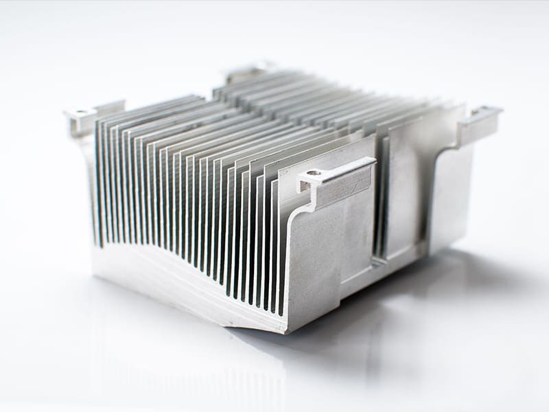
Quick Answer: Heat sinks remove heat from electronic components through two sequential mechanisms: conduction transfers heat from the component through a thermal interface material into the heat sink body and across its base; convection dissipates that heat from the fin surface area into surrounding air. Radiation provides a supplementary 5–10% contribution. Performance is quantified by thermal resistance (Rθ = ΔT / Q in °C/W) — lower resistance means more effective cooling. Material, fin geometry, airflow conditions, and thermal interface quality are the four variables that determine whether a heat sink meets its thermal requirement.
What Is a Heat Sink?
A heat sink is a passive thermal component designed to absorb heat from a heat-generating device and transfer it to a fluid medium — typically air — at a rate sufficient to keep the device below its maximum junction temperature. Without controlled heat dissipation, power semiconductors, CPUs, LEDs, and motor control electronics experience thermal throttling, accelerated degradation, and ultimately premature failure.
Heat sinks are passive devices in their basic form — they operate without moving parts, consuming no power and requiring no maintenance. Their effectiveness depends entirely on design: the thermal conductivity of the base material, the surface area created by fin geometry, the airflow conditions at the fin surfaces, and the quality of thermal coupling between the heat source and the heat sink base.
For engineers designing power electronics, LED modules, automotive control units, and computing systems, the heat sink is not a separate accessory — it is an integral part of the thermal management system that must be specified alongside the component it cools, not selected after layout is complete.
How Do Heat Sinks Work? The Four-Stage Thermal Path
Heat moves from a component through a heat sink to the environment in four distinct stages. Each stage has its own governing physics, failure modes, and engineering variables.
Stage 1: Heat Generation at the Component
Electronic components convert a fraction of their input electrical power to heat — this is unavoidable for any device with non-zero electrical resistance. A MOSFET switching 500 W at 98% efficiency dissipates 10 W as heat. A CPU drawing 125 W converts essentially all of that to heat at the die level. An LED at 50% wall-plug efficiency dissipates half its electrical input as heat from a junction area measured in square millimeters.
The critical engineering parameter at this stage is heat flux — watts per unit area at the device’s thermal contact surface. High heat flux (concentrated power in a small area) is more challenging to manage than an equivalent power level distributed over a larger area.
Stage 2: Conduction Through the Thermal Interface Material
Between the component’s thermal pad and the heat sink base, microscopic surface irregularities prevent full metal-to-metal contact. The air gaps that fill these irregularities have thermal conductivity of approximately 0.026 W/(m·K) — one order of magnitude lower than the best thermal interface materials and two to three orders of magnitude lower than the metal substrates. Unfilled air gaps create thermal resistance that can easily dominate the entire thermal path.
Thermal interface materials (TIMs) — thermal grease, phase-change materials, graphite pads, indium foil — fill these microscopic voids with materials having thermal conductivity of typically 1–20 W/(m·K) for common commercial TIMs, and 50–80 W/(m·K) for high-performance options like thermal compounds with diamond or silver loading.
TIM selection and application directly determines the thermal interface resistance:
- Dry contact (no TIM): approximately 0.5–2.0 °C/W for typical surface finishes
- Thermal grease (standard, ~1–4 W/m·K): approximately 0.1–0.5 °C/W
- High-performance TIM (>10 W/m·K): approximately 0.05–0.2 °C/W
In our production experience with power electronics assemblies, inadequate TIM application — insufficient coverage, air inclusions, or wrong thickness — is one of the most common root causes of thermal underperformance in systems with correctly specified heat sinks. The best heat sink design cannot compensate for a poorly executed thermal interface.
Stage 3: Conduction and Spreading Within the Heat Sink
Once heat enters the heat sink base, it must spread laterally from the concentrated contact area to the full base plate area and then vertically into the fins. Two mechanisms govern this:
Thermal conductivity of the base material determines how quickly heat spreads. Higher conductivity produces lower temperature gradients in the base, ensuring heat reaches the outer fins rather than concentrating near the center. Aluminum (~200–220 W/m·K) spreads heat reasonably well for most applications; copper (~380–400 W/m·K) spreads heat approximately twice as fast, which is why copper bases are used when the heat source is much smaller than the heat sink footprint.
Spreading resistance is the additional thermal resistance caused by the temperature gradient required to spread heat from a small source area to a larger dissipation area. For a CPU die covering 20% of the heat sink base area, spreading resistance can contribute 0.1–0.3 °C/W to the total thermal resistance — significant for high-performance systems.
Stage 4: Convection from Fin Surfaces to Air
The fins serve one purpose: maximizing the surface area available for convective heat transfer to air. The governing relationship is:
Q = h × A × ΔT
Where h is the convective heat transfer coefficient (W/m²·K), A is the fin surface area (m²), and ΔT is the temperature difference between the fin surface and the ambient air (°C). For natural convection in still air, h is approximately 5–25 W/m²·K. For forced convection with a fan delivering 1–3 m/s air velocity over the fins, h increases to approximately 50–150 W/m²·K — producing 5–10× higher heat transfer for the same surface area.
This convection coefficient difference explains why the same heat sink can handle 25 W passively and 150 W with a fan — not because the fan improves the heat sink structure, but because forced convection dramatically increases h.
Thermal Radiation: The Supplementary Contributor
Radiation heat transfer is proportional to the fourth power of absolute temperature and the material’s emissivity. At typical electronics operating temperatures (60–100°C surface temperature), radiation contributes approximately 5–10% of total heat dissipation. Black anodized surfaces have emissivity of approximately 0.8–0.9 versus 0.05–0.1 for polished aluminum, making black anodizing beneficial for passive heat sinks where radiation’s contribution is more significant.
Key Factors That Determine Heat Sink Performance
1. Material Thermal Conductivity
Material selection determines the speed of heat spreading from the source through the base to the fins.
| Material | Thermal Conductivity (W/m·K) | Density (g/cm³) | Relative Cost |
|---|---|---|---|
| Aluminum 6061 | ~200–220 | 2.70 | Low |
| Aluminum 1050 (pure) | ~220–230 | 2.71 | Low |
| Copper C110 | ~385–400 | 8.96 | High |
| Graphite (in-plane) | ~700–1500 | 2.10 | Medium–High |
| Diamond composite | ~400–600 | ~3.5 | Very High |
Aluminum dominates commercial heat sink production because it combines acceptable thermal conductivity with low density, ease of extrusion, and low cost. For applications where the heat source area is significantly smaller than the heat sink base — producing high spreading resistance — copper’s higher conductivity reduces the temperature gradient in the base, justifying its higher cost and weight.
2. Surface Area Through Fin Geometry
Fins multiply the effective heat transfer surface area relative to the heat sink base area. A flat plate with 0.01 m² base area might present 0.01 m² to the airstream; adding 20 fins of height 40 mm and 0.5 mm thickness over a 100 mm length increases the effective surface area by approximately 10–15×.
The geometry variables that optimize convective surface area:
Fin height: Taller fins increase surface area but create longer thermal path from base to fin tip, which increases the temperature gradient along the fin (fin efficiency decreases). For typical aluminum fins with natural convection, optimal fin height is approximately 30–60 mm; beyond this, incremental area gain diminishes because fin tip temperature approaches ambient before contributing meaningfully.
Fin thickness: Thinner fins allow more fins per unit width (more surface area) but reduce heat conduction along the fin and structural integrity. Typical extruded aluminum fin thickness ranges from 1.0–2.5 mm.
Fin spacing: Critical for airflow management. For natural convection, wider spacing (6–12 mm gap) allows the buoyancy-driven air column to establish; too-close fins create excessive flow resistance. For forced convection, tighter spacing (2–5 mm gap) is effective because the fan overcomes the pressure drop.
3. Airflow Conditions
The difference between natural and forced convection is not incremental — it is a step change in heat transfer capacity:
| Airflow Condition | Typical h (W/m²·K) | Relative Performance |
|---|---|---|
| Still air (natural convection) | 5–15 | Baseline |
| Light natural convection (vented enclosure) | 10–25 | 1.5–2× |
| Fan at 1 m/s | 50–80 | 5–8× |
| Fan at 3 m/s | 100–150 | 10–15× |
| Liquid cooling loop | 1,000–5,000 | 100–500× |
The orientation of fins relative to airflow direction is as important as the airflow velocity. Fins aligned parallel to airflow direction have significantly lower pressure drop than fins perpendicular to flow, allowing more air volume to pass through for the same fan power. Vertical fins in natural convection applications allow thermal buoyancy to drive air upward through the fin channels without external fans.
4. Thermal Interface Quality
No engineering factor causes more avoidable heat sink performance failure than thermal interface management. The thermal resistance of the interface between device and heat sink can exceed the thermal resistance of the heat sink itself if not properly executed.
Best practices:
- Flatness of both mating surfaces to ≤ 0.025 mm per 25 mm for optimal TIM function
- Minimum effective TIM layer — thinner is better for high-conductivity TIMs; typical target 0.05–0.15 mm
- Full coverage with no air inclusions
- Consistent mounting pressure (torque specifications exist for a reason — too little leaves air gaps; too much squeezes out TIM and cracks ceramic packages)
Thermal Resistance: Quantifying Heat Sink Performance
Thermal resistance is the single number that characterizes heat sink performance, enabling engineers to calculate component junction temperature from heat dissipation and ambient temperature.
Rθ = ΔT / Q (°C/W)
Where ΔT is the temperature difference across the thermal element (°C) and Q is the heat flow through it (W). Lower thermal resistance means better cooling — more heat is transferred for the same temperature difference.
The total thermal resistance from component junction to ambient air is the sum of all resistances in the thermal path:
Rθ_total = Rθ_junction-case + Rθ_interface + Rθ_heat-sink + Rθ_ambient
For a 100 W power module with Rθ_total = 0.8 °C/W at 25°C ambient:
- Component temperature = 25 + (100 × 0.8) = 105°C
- If the component’s maximum junction temperature is 125°C, there is 20°C margin
Changing to a heat sink with Rθ_heat-sink = 0.4 °C/W (instead of 0.6 °C/W) reduces total Rθ_total to 0.6 °C/W:
- Component temperature = 25 + (100 × 0.6) = 85°C
- Margin increases to 40°C
Typical thermal resistance targets by application:
| Application | Target Rθ (°C/W) | Notes |
|---|---|---|
| High-performance CPU cooling | < 0.3 | Liquid cooling or large active heat sink |
| Server/computing active cooling | 0.3–0.8 | Fan + heat sink combinations |
| Industrial power electronics | 0.5–2.0 | Depends on power and size |
| LED passive cooling | 1–5 | Low power; passive adequate |
| General passive electronics | > 2 | Low heat loads |
Heat Sink Types: Passive, Active, and Hybrid
Passive Heat Sinks
Passive heat sinks use natural convection exclusively — no fans or forced airflow. They are silent, consume no power, and have no mechanical failure modes. The practical limitation is heat transfer capacity: typical passive heat sinks effectively dissipate 5–50 W depending on size and fin geometry. Applications include LED modules, low-power linear regulators, small motor drives, and telecommunications equipment where fan noise is unacceptable.
Design for passive cooling requires particular attention to fin orientation (vertical fins strongly outperform horizontal fins by enabling buoyancy-driven flow), enclosure ventilation (blocked air inlets destroy passive convection), and adequate fin height (taller fins are more effective for natural convection than shorter dense fins).
Active Heat Sinks
Active heat sinks add mechanical airflow — a fan, blower, or ducted air supply — to the fin array. The increased convection coefficient (5–15× natural convection) enables the same heat sink to dissipate 5–15× more heat, or the same heat load to be managed with a much smaller heat sink. This is why virtually all CPUs above 35 W use active cooling.
The trade-offs of active cooling are fan noise (typically 25–45 dBA for CPU coolers), power consumption (typically 2–15 W for fans, small relative to the heat being managed), mechanical complexity (bearings, impellers, motor electronics), and finite fan service life (typically 20,000–50,000 hours for quality ball-bearing fans).
Hybrid Thermal Management
Advanced applications combine passive and active elements: heat pipes or vapor chambers spread heat from concentrated sources across larger areas before conventional fin arrays dissipate it; thermoelectric coolers (Peltier devices) provide localized active cooling below ambient temperature; liquid cooling loops replace air with water or dielectric fluid as the convective medium for data centers, EV traction inverters, and high-performance computing clusters.
For CNC-machined custom heat sinks supporting power levels above 500 W per device, the effective thermal management strategy typically involves copper-aluminum hybrid construction (copper base for spreading, aluminum fins for dissipation), combined with forced convection from fan or liquid-assisted systems.
Aluminum vs Copper Heat Sinks: Selection Guide
When Aluminum Is the Correct Choice
Aluminum is the dominant commercial heat sink material because it optimizes the balance of thermal performance, weight, cost, and manufacturability for the majority of applications. At 200–220 W/(m·K) thermal conductivity, aluminum handles most power electronics and computing heat loads when the heat source covers a significant fraction of the heat sink base area. Its density of 2.70 g/cm³ (approximately one-third of copper) keeps weight manageable in weight-sensitive applications. And its excellent extrudability allows complex fin profiles to be produced at high volume with low tooling cost.
Choose aluminum for:
- Consumer electronics, LED lighting, general industrial electronics
- Applications where source area ≥ 30% of heat sink base area
- High-volume production where per-part cost is critical
- Weight-sensitive designs (aerospace, portable equipment)
When Copper Justifies Its Premium
Copper’s 380–400 W/(m·K) thermal conductivity is approximately 1.8× aluminum’s, producing proportionally lower temperature gradients in the base when heat must spread from a small source to a larger fin array. For a CPU die of 15 × 15 mm mounted to a 100 × 100 mm heat sink, the spreading resistance in a copper base can be 30–40% lower than in aluminum — a meaningful difference for high-performance systems.
Choose copper for:
- High heat flux sources (small die area, high wattage)
- Applications where spreading resistance is a significant fraction of total resistance
- Compact designs where size constraints limit heat sink footprint
- Hybrid constructions: copper base plate + aluminum fin stack
Hybrid Heat Sink Construction
The most thermal-efficiency-optimized heat sinks combine copper base plates (where spreading resistance reduction benefits most) with aluminum fin arrays (where weight and cost savings are largest). This combination appears in high-performance CPU coolers, IGBT module coolers for industrial drives, and EV power electronics. The engineering trade-off for each assembly is straightforward: calculate the thermal resistance contribution of base spreading versus fin convection, and apply the more conductive material where spreading dominates.
Heat Sink Manufacturing Methods
Manufacturing method determines achievable fin geometry, dimensional accuracy, surface quality, and production economics. Each method has a distinct optimal application range.
Aluminum Extrusion
Extruded aluminum heat sinks are produced by forcing heated aluminum billet through a precision die, producing a continuous profile that is cut to length. This is the most cost-effective production method for straight-fin heat sinks in medium to high volumes. Typical achievable fin height-to-thickness ratios (aspect ratios) are 8:1 to 20:1 depending on die design complexity and alloy.
Best for: Standard straight-fin designs, medium-to-high volume production, cost-sensitive applications. Limitations: straight fins only (no pin arrays, no skived fins), moderate fin thickness achievable.
CNC Machining
CNC machining removes material from aluminum or copper billet to create custom heat sink geometry. This is the highest-precision and highest-flexibility method, capable of producing complex fin patterns, integrated mounting features, machined channels for heat pipes, and hybrid copper-aluminum assemblies. Tool path programming allows any fin geometry that is physically accessible to cutting tools.
Best for: Custom prototypes, low-to-medium volume production, complex geometry, high-performance applications, hybrid metal assemblies. Limitations: higher cost per part than extrusion for simple geometries; longer lead times for custom tooling.
Die Casting
Die-cast aluminum heat sinks are produced by injecting molten aluminum into a steel mold under high pressure. This enables complex three-dimensional geometries with integrated features — mounting bosses, through-holes, complex fin arrangements in multiple directions — not achievable with extrusion. The limitation is that die casting produces slightly lower thermal conductivity than extruded or machined aluminum due to the microstructure of the rapidly solidified casting.
Best for: Complex geometry, integrated housings, medium volume production. Limitations: lower thermal conductivity (~96–100 W/m·K for typical die-cast alloys, approximately 40–50% lower than extruded 6061), higher tooling cost.
Manufacturing Method Comparison
| Method | Cost | Fin Complexity | Thermal Performance | Best Application |
|---|---|---|---|---|
| Extrusion | Low (volume) | Medium (straight fins) | Good | Standard electronics cooling |
| CNC machining | Higher | High (any geometry) | Excellent | Custom, high-performance |
| Die casting | Medium | High (3D geometry) | Moderate | Complex integrated housings |
| Skiving | Medium | Very high (thin dense fins) | Excellent | High-density cooling |
Design Principles for Optimal Heat Sinks
Thermal Resistance as the Design Target
Every heat sink design should begin with a thermal budget: what maximum junction temperature is allowed, what is the ambient air temperature, what is the power to be dissipated, and what thermal resistance does the interface contribute? From these numbers, the required heat sink thermal resistance is directly calculable:
Rθ_heat-sink = (T_junction_max − T_ambient − Q × Rθ_interface) / Q
Working backward from this required Rθ_heat-sink, the fin geometry and material can be selected to meet the requirement. This disciplined approach prevents both under-design (thermal failure) and over-design (unnecessary cost and weight).
Fin Geometry Rules of Thumb
- Natural convection: Fin spacing 6–12 mm, fin height 30–60 mm, fins oriented vertically. Wider spacing is better than narrower for the same fin height in natural convection.
- Forced convection: Fin spacing 2–5 mm, fin height limited by fan pressure capability, fins aligned parallel to airflow direction. Tighter spacing is acceptable because the fan overcomes pressure drop.
- Pin fins: Effective for omnidirectional airflow environments and circular flow patterns from fans; less optimal than plate fins for unidirectional flow.
Common Design Mistakes
Blocking airflow: Enclosure design that concentrates the heat sink in a sealed cavity without inlet/outlet paths for air destroys natural convection and severely limits forced convection. The heat sink and its airflow path are a system — the enclosure design must be part of the thermal design.
Undersized thermal interface contact area: Mounting a heat sink to a component through a contact pad smaller than the component’s thermal pad wastes the heat sink’s effective area. The heat sink base area should match or exceed the component’s thermal contact area.
Wrong fin orientation for natural convection: Horizontal fins obstruct buoyancy-driven air flow vertically. Vertical fins allow natural convection to establish from bottom to top through the fin channels. This single design change can double natural convection performance.
Ignoring thermal resistance budget: Selecting a heat sink by size (“bigger is better”) rather than by thermal resistance calculation leads to inconsistent results — a large aluminum heat sink may underperform a smaller copper one for a concentrated high-flux source, because spreading resistance is the dominant term in the total thermal path.
Applications
CPU and Computing
Modern desktop CPUs dissipate 65–250 W in a die area of approximately 15–25 mm², producing heat fluxes of 100–400 W/cm². This concentration requires effective heat spreading from the CPU die through the integrated heat spreader (IHS), then through the TIM to the cooler base, then via convection from the fin array. Consumer CPU coolers achieve Rθ of 0.1–0.5 °C/W in typical active configurations; high-end liquid coolers reach 0.05–0.15 °C/W.
Power Electronics (IGBTs, MOSFETs, Motor Drives)
Power conversion equipment generates substantial heat in the switching devices. A 10 kW motor drive with 98% efficiency dissipates 200 W. Industrial drive heat sinks for IGBT modules are typically large aluminum extrusions with dedicated fans, designed to maintain junction temperature below 125°C at maximum load. The heat sink is often the largest single component in the drive assembly.
LED Lighting
High-power LED modules convert 40–60% of electrical input to light and the remainder to heat. Unlike CPUs, LED systems typically operate without fans to eliminate noise and mechanical maintenance, placing heavy requirements on passive heat sink design. LED heat sinks are typically optimized for natural convection with vertical fins, maximum base plate coverage, and black anodized surfaces to enhance radiation contribution.
Automotive Electronics
Automotive electronic control units (ECUs), EV power inverters, and battery management systems operate in challenging thermal environments — elevated ambient temperatures (85–105°C under-hood), limited airflow, vibration, and reliability requirements that preclude fan-based cooling in most locations. Aluminum heat sinks bonded or bolted to the vehicle body or chassis structure are common, using the body structure as a large thermal mass and heat spreader.
Key Takeaways
- Heat sinks remove heat through conduction (source to heat sink body) and convection (heat sink body to air), with radiation providing a secondary contribution of 5–10%.
- Thermal resistance (Rθ = ΔT/Q in °C/W) is the quantitative measure of heat sink performance — lower is better. All thermal design should start with a Rθ budget calculated from junction temperature limit, ambient temperature, and power dissipation.
- The thermal interface between component and heat sink is frequently the weakest link in the thermal path. Proper TIM selection, application technique, and mounting pressure are as important as the heat sink itself.
- Fin geometry determines convective surface area: height, thickness, spacing, and orientation must be matched to the airflow regime (natural or forced convection).
- Aluminum is the correct choice for most applications — it offers an excellent balance of thermal conductivity, weight, cost, and manufacturability. Copper is justified for high heat flux sources or applications where spreading resistance dominates.
- Natural convection heat sinks must have vertical fins and clear airflow paths; forced convection multiplies effective heat transfer coefficient by 5–15× but introduces fan complexity.
- For OEM procurement teams, specifying heat sink thermal resistance (°C/W) and the required test conditions (power, airflow, ambient temperature) is more useful than specifying physical dimensions alone — it ensures the supplied heat sink meets the functional thermal requirement regardless of the specific geometry.
Frequently Asked Questions
How do heat sinks work to cool electronics?
Heat sinks remove heat from electronic components through two primary mechanisms. First, conduction transfers heat from the component through a thermal interface material (TIM) into the heat sink base, then spreads laterally through the base to the fin array. Second, convection transfers that heat from the fin surface area to the surrounding air — either through natural convection (buoyancy-driven airflow in still air) or forced convection (fan-assisted airflow). Radiation contributes an additional 5–10% at typical operating temperatures. The effectiveness of each stage is characterized by thermal resistance: junction-to-case resistance (device-specific), interface resistance (TIM-dependent), and heat-sink-to-ambient resistance (the heat sink’s performance specification).
What is thermal resistance in heat sinks and why does it matter?
Thermal resistance (Rθ, measured in °C/W) describes how much temperature rise occurs for each watt of heat flowing through a thermal element. A heat sink with Rθ = 1 °C/W increases temperature by 1°C for every watt dissipated; Rθ = 0.5 °C/W increases temperature by 0.5°C per watt. Lower thermal resistance means better cooling. Total junction temperature equals ambient temperature plus the product of total thermal resistance and power dissipation: T_junction = T_ambient + Q × Rθ_total. This relationship allows engineers to calculate whether a specific heat sink keeps the component below its maximum rated temperature before any hardware is built.
What is the difference between aluminum and copper heat sinks?
Aluminum (200–220 W/m·K) is the standard heat sink material — lightweight, inexpensive, easily extruded, and thermally adequate for the majority of electronics cooling applications. Copper (380–400 W/m·K) has approximately 1.8× higher thermal conductivity, making it superior for applications where the heat source is much smaller than the heat sink footprint (where heat must spread over a long distance) or where thermal resistance must be minimized in a compact design. Copper is heavier (8.96 g/cm³ vs 2.70 g/cm³) and more expensive. Hybrid designs using a copper base plate with aluminum fins balance copper’s spreading advantage with aluminum’s weight and cost advantages — commonly used in high-performance CPU coolers and industrial power electronics.
What is the difference between passive and active heat sinks?
Passive heat sinks rely on natural convection — temperature-driven buoyancy moves air across the fin surfaces without any mechanical assistance. They are silent, require no power, and have no moving parts to fail. Practical passive cooling limits are approximately 5–50 W depending on heat sink size and fin geometry. Active heat sinks add a fan or blower that forces air through the fin array, increasing the convective heat transfer coefficient by 5–15× over natural convection. This enables the same heat sink to dissipate 5–15× more heat, or allows a smaller heat sink to handle the same load. The trade-offs are fan noise (25–45 dBA typical), power consumption (2–15 W typical), and finite fan service life.
How do I select the right heat sink for my application?
Start with a thermal budget: determine the maximum allowed junction temperature (from the component datasheet), the maximum ambient temperature, and the power to be dissipated. Calculate the required total thermal resistance: Rθ_total = (T_junction_max − T_ambient) / Q. Subtract the device junction-to-case resistance (from datasheet) and the interface resistance (from TIM specification) to get the required heat-sink-to-ambient resistance. Select a heat sink with rated Rθ at or below this requirement under your specific airflow conditions. For passive systems, verify the rated Rθ is under natural convection; for fan-cooled systems, verify the rating matches your fan’s airflow velocity or static pressure capability.
Written by the CMS engineering team with 15+ years of CNC machining and thermal component manufacturing experience for power electronics, LED systems, automotive ECUs, and industrial automation OEM applications. Technical references: JEDEC JESD51 (Thermal Measurement Methodology), IPC-2221 (Generic Standard on Printed Board Design — Thermal Considerations), ASHRAE Data Center Cooling Guidelines, Incropera’s Fundamentals of Heat and Mass Transfer.
Sourcing CNC Machined Custom Heat Sinks for Power Electronics or LED Applications?
At CMS, we machine custom aluminum and copper-aluminum hybrid heat sinks from engineering drawings, with DFM review for fin geometry, mounting feature integration, and thermal performance feasibility. Every custom heat sink project includes a review of required thermal resistance versus achievable geometry before machining begins.
[Request a DFM review and custom heat sink machining quote →]


