
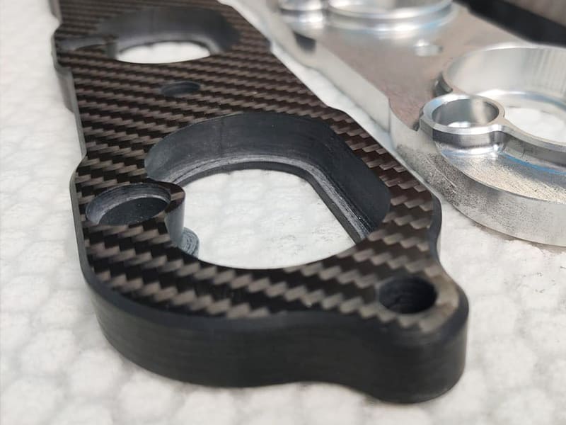
Carbon fiber composites are very strong, stiff, and light, but they are hard to machine because their fibers are rough and they are made up of layers. To get clean edges, tight tolerances, and a consistent surface quality, you need the right tools, cutting parameters, and ways to control dust.
This guide covers the most important engineering practices for CNC carbon fiber machining, such as choosing the right tools, planning machining operations, and improving surface quality. This will help you make composite parts that are accurate and reliable.
Why CNC Machining Matters for Carbon Fiber Components
Carbon fiber reinforced polymers (CFRP) have become one of the most advanced structural materials in modern engineering, known for their exceptional strength-to-weight ratio, high stiffness, and excellent fatigue resistance. These properties make CFRP indispensable in industries such as aerospace, automotive, robotics, drones, medical devices, and high-performance sporting equipment, where performance, precision, and lightweight design are critical.
However, while carbon fiber composites offer unmatched mechanical advantages, their anisotropic and abrasive nature presents unique challenges in manufacturing. Unlike metals, CFRP cannot be formed or machined using conventional methods without risk of fiber delamination, resin chipping, or thermal degradation. This is where CNC machining technology plays a crucial role—providing the precision, repeatability, and process control necessary to transform carbon fiber laminates or blocks into complex, dimensionally stable components.
The Role of CNC Machining in Carbon Fiber Manufacturing
CNC machining allows engineers to achieve micron-level accuracy in contouring, drilling, milling, and trimming of carbon fiber parts—operations that are essential for tight-tolerance assemblies such as aerospace brackets, UAV frames, optical mounts, and robotic joints. By using high-speed spindles, diamond-coated tools, and adaptive control systems, CNC machines can maintain edge quality and surface finish even under high tool wear conditions.
Key advantages of CNC machining for CFRP include:
-
Complex geometry realization: Enables creation of intricate contours, holes, and cutouts that cannot be achieved through molding alone.
-
Dimensional consistency: Ensures repeatable accuracy across production batches, critical for aerospace and automotive certification.
-
Hybrid integration: Facilitates secondary machining on carbon-fiber–metal hybrid parts, such as titanium inserts or aluminum fixtures.
-
Surface quality control: Maintains tight tolerances and minimizes fiber pull-out or matrix cracking through controlled cutting parameters.
Understanding Carbon Fiber Composites and Machining Behavior
Structure and Material Characteristics
Carbon fiber reinforced polymers (CFRP) are advanced composite materials made from high-strength carbon fibers embedded in a polymer matrix, typically epoxy, PEEK, or BMI resins. The carbon fibers provide structural stiffness and strength, while the resin binds and transfers load between fibers. This layered structure offers an exceptional strength-to-weight ratio, far exceeding that of metals like aluminum or steel.
The fiber layup configuration—such as unidirectional (UD), woven, or quasi-isotropic—significantly affects machinability:
-
Unidirectional laminates: Provide maximum strength along the fiber direction but are prone to splintering and delamination when cut across fibers.
-
Woven fabrics: Offer better dimensional stability but produce irregular tool loads due to alternating fiber orientations.
-
Quasi-isotropic laminates: Achieve balanced strength in multiple directions but still present variable chip formation across layers.
Due to the combination of brittle resin and high-stiffness fibers, machining CFRP differs fundamentally from metals. Cutting forces are localized and discontinuous, increasing the risk of fiber pull-out, matrix cracking, and delamination if not properly controlled.
Mechanical and Thermal Properties
| Property | Typical Range | Machining Implication |
| Tensile Strength | 500–1500 MPa | High rigidity → Difficult to shear or cut |
| Flexural Modulus | 60–200 GPa | Low interlaminar toughness → Delamination risk |
| Thermal Conductivity | 5–20 W/m·K | Poor heat dissipation → Localized thermal damage |
| Density | ~1.6 g/cm³ | Lightweight → Higher vibration sensitivity |
-
High strength and stiffness make CFRP resistant to deformation, but the lack of ductility leads to brittle fracture rather than plastic deformation during cutting.
-
Low thermal conductivity means that cutting heat remains concentrated near the tool–work interface, potentially softening or charring the resin matrix.
-
Low density contributes to part vibration, which can worsen surface finish and dimensional accuracy in thin-walled geometries.
Engineering note: To counteract these challenges, precise control of spindle speed, feed rate, and tool geometry is essential, along with vibration damping and cooling strategies.
Machining Challenges Unique to CFRP
CFRP machining presents a distinct set of challenges not encountered in metals or plastics:
-
High abrasiveness: Carbon fibers act like microscopic grinding elements, accelerating tool wear—especially on carbide or HSS tools. Diamond-coated or PCD tools are preferred for extended tool life.
-
Delamination and fiber pull-out: Poorly optimized cutting parameters or blunt tools can lift layers apart, reducing structural integrity.
-
Fine dust generation: Micron-sized carbon dust poses health and contamination risks to equipment; vacuum extraction and sealed machining environments are essential.
-
Thermal degradation: Excessive heat can cause matrix softening, resin microcracking, or discoloration, especially in epoxy-based CFRP.
In summary: Carbon fiber composites combine exceptional mechanical performance with unique machining complexities. A deep understanding of their anisotropic structure and thermal behavior is crucial for selecting the right CNC machining strategy—balancing precision, tool longevity, and surface integrity.
Tooling Selection and Cutting Parameters for CNC Carbon Fiber
Recommended Tool Types
| Tool Type | Application Scenario | Advantages | Limitations |
| PCD (Polycrystalline Diamond) | High-volume / finish machining | Extreme wear resistance, ultra-smooth cutting | Very high cost |
| CVD Diamond-Coated Carbide | General precision machining | Excellent cost-performance balance | Coating may delaminate under impact or high temperature |
| Uncoated Carbide | Prototyping / low-volume runs | Economical, easily available | Rapid wear due to fiber abrasiveness |
Engineering insight: For long production runs or aerospace-grade CFRP, PCD tools are the industry standard, capable of maintaining sharpness for tens of meters of cutting length. For general-purpose or low-volume machining, CVD diamond-coated carbide tools provide the best compromise between durability and affordability. Uncoated carbide tools are only recommended for short runs, prototyping, or setup trials, where cost control outweighs tool longevity.
Tool geometry also plays a decisive role:
-
Positive rake angles (10–15°) minimize delamination by reducing cutting forces.
-
High helix angles improve chip evacuation in milling and slotting.
-
“Brad point” or step drills help prevent fiber breakout during drilling operations.
Cutting Parameters Guidelines
| Process | Spindle Speed (RPM) | Feed Rate (mm/min) | Depth of Cut (mm) |
| Milling | 15,000–30,000 | 800–1500 | 0.1–0.5 |
| Drilling | 5,000–10,000 | 100–300 | 0.05–0.3 |
| Slotting / Contouring | 10,000–20,000 | 500–1000 | 0.2–0.8 |
-
Climb milling (down-cut milling) is strongly recommended for CFRP as it reduces fiber lifting, delamination, and edge fraying by applying compressive cutting forces on the laminate surface.
-
Use minimum quantity lubrication (MQL) or cold air cooling instead of conventional flood coolant, as excessive moisture or temperature changes can damage the resin matrix.
-
Frequent tool condition monitoring is essential—PCD edges should be inspected under a microscope every few hours of cutting to prevent sudden delamination failures.
Typical surface finish results: With optimized conditions and PCD tooling, Ra ≤ 1.6 µm is achievable for milled surfaces and hole roundness ≤ 0.05 mm for drilled features.
Fixturing and Vibration Control
-
Vacuum tables provide uniform clamping without mechanical stress, ensuring CFRP sheets or laminates remain flat and stable during high-speed machining.
-
Use damping bases or backer plates (e.g., phenolic resin or aluminum) beneath the workpiece to absorb vibration and prevent fiber breakout on the exit side.
-
For thick or multi-layer components, support the underside using soft fixtures or elastomer layers to minimize interlaminar stress.
-
Fixture contact areas should avoid direct exposure to cutting heat zones, as localized temperature rise may lead to matrix softening or deformation.
Engineering takeaway: Successful CNC carbon fiber machining depends on a holistic approach—choosing the right diamond tooling, maintaining optimized spindle speed and feed rates, and implementing precision fixturing with vibration damping. This integration ensures dimensional accuracy, minimal fiber damage, and extended tool life, essential for aerospace and high-performance composite manufacturing.
Dust Control, Safety, and Machine Requirements
Dust Extraction and Filtration
CNC machining of carbon fiber generates fine, conductive, and abrasive dust particles that can damage electronic components and pose health risks. Therefore, an advanced dust control system is essential to maintain both operator safety and machining precision.
-
HEPA filtration systems (High-Efficiency Particulate Air): Use vacuum units equipped with HEPA filters (H13 or higher) capable of capturing ≥99.97% of particles down to 0.3 μm.
-
Negative-pressure extraction: Maintain continuous negative air pressure inside the machining enclosure to prevent dust leakage into the workshop environment.
-
Separation zones: Physically isolate the machining chamber from the CNC’s electronics cabinet and servo drives to prevent conductive dust contamination, which could lead to short circuits or insulation failures.
-
Inline cyclonic pre-filters may also be used before HEPA stages to extend filter life in high-volume operations.
⚙️ Best practice: Integrate dust extraction with the spindle head or toolpath area to capture particles at the source, reducing airborne dispersion and improving machine reliability.
Operator and Environmental Safety
Machining carbon fiber requires strict adherence to occupational health and environmental safety standards due to the material’s fiber composition and airborne particulate hazards.
-
Personal protective equipment (PPE): Operators must wear P3-rated respirators, protective goggles, and anti-static clothing to prevent inhalation and skin irritation.
-
Enclosed machining chambers: Fully enclosed CNC machines or sealed robotic cells are strongly recommended for carbon composite processing.
-
Air quality monitoring: Regularly measure airborne carbon dust concentration to ensure compliance with workplace exposure limits (e.g., OSHA or EU REACH standards).
-
Routine machine maintenance: Clean dust extraction ducts weekly and replace filters as per manufacturer intervals.
-
Spindle sealing replacement: Regularly inspect and replace spindle seals to prevent dust ingress that may cause bearing wear or motor failure.
Machine Setup and Maintenance
CFRP machining requires high-speed, high-stiffness CNC systems capable of maintaining consistent cutting quality despite abrasive conditions.
-
High-speed spindles: Machines should support spindle speeds of >20,000 RPM, essential for fine cutting and reduced delamination during milling and drilling.
-
Rigid structure and vibration damping: Carbon fiber’s low density amplifies vibration; thus, CNC machines must feature reinforced bases, damped axes, and precision linear guides.
-
Dry or air-cooled cutting: Avoid liquid coolant—carbon fiber dust mixed with liquid forms a conductive slurry that can damage electronic parts and degrade resin bonds.
-
Regular tool inspection: Measure tool wear and surface roughness every few hours to detect performance deviations early. Dull tools drastically increase fiber tear-out and delamination.
-
Clean airflow management: Maintain filtered, dry air for cooling and chip evacuation to prevent contamination and static buildup.
Engineering takeaway: CNC carbon fiber machining requires a controlled environment that balances precision, cleanliness, and safety. Robust dust extraction, sealed enclosures, and disciplined maintenance not only protect operators and equipment but also ensure consistent surface quality and dimensional accuracy in advanced composite manufacturing.
Surface Finish, Dimensional Accuracy, and Quality Control
Edge and Surface Integrity
Achieving a high-quality surface on CNC-machined carbon fiber parts requires precise control of toolpath strategy, fiber orientation, and cutting parameters. Because CFRP is anisotropic, the cutting direction relative to fiber alignment has a direct impact on delamination and edge chipping.
-
Optimal cutting angle: Maintaining a 45°–90° approach angle relative to the fiber direction minimizes tensile stress at the fiber–matrix interface, reducing the risk of delamination and pull-out.
-
Multi-pass finishing: Use light, multiple finishing passes (0.05–0.1 mm per pass) to improve surface smoothness and reduce localized fiber damage.
-
Surface roughness benchmarks: Precision carbon fiber components typically achieve Ra = 0.8–1.6 µm, depending on tool sharpness, feed rate, and fiber type.
Engineering note: Excessive tool wear or cutting at low angles can expose fibers, causing “fuzzy edges” that degrade aesthetics and performance. A controlled finishing strategy ensures clean edges and consistent sealing surfaces for bonded or assembled parts.
Inspection and Defect Detection
Defects in machined CFRP components are often microscopic or subsurface, requiring specialized non-destructive and microscopic inspection techniques.
| Defect Type | Detection Method | Notes |
| Delamination | Ultrasonic testing / Acoustic emission | Identifies interlaminar separation or voids between plies |
| Fiber Pull-Out | Optical microscopy / SEM | Evaluates surface integrity and fiber–matrix adhesion |
| Burn Marks / Heat Damage | Visual inspection / Infrared thermography | Detects localized thermal degradation and resin discoloration |
Additional methods such as X-ray computed tomography (CT scanning) can be used for advanced aerospace parts to detect voids, resin pockets, and structural inhomogeneities.
Tip for production engineers: Implement inspection checkpoints after roughing and finishing stages to isolate process-induced defects before final assembly.
Dimensional and Structural Verification
High-precision CFRP components require multi-dimensional validation to confirm geometric and structural accuracy:
-
Coordinate Measuring Machine (CMM): Provides ±0.005 mm accuracy for hole positions, contours, and flatness of complex parts.
-
Laser Scanning / Optical Profiling: Enables rapid non-contact verification of large or curved CFRP surfaces without mechanical probing.
-
Material composition verification: Follow ASTM D3171 or EN 2563 standards to measure fiber volume fraction (Vf), ensuring consistent mechanical performance across production batches.
Engineering insight: Because CFRP exhibits thermal expansion anisotropy, all dimensional inspections should be performed under controlled temperature and humidity (typically 20 °C ±1 °C, RH <50%) to maintain metrological accuracy.
Design and DFM Considerations for Carbon Fiber CNC Parts
Design-for-Manufacturability Guidelines
Designing CNC-machined carbon fiber components requires understanding the material’s anisotropic structure and brittle fracture behavior. Because carbon fibers carry load mainly along their length, design geometry and fiber orientation directly affect manufacturability and structural integrity.
-
Hole design: Keep hole diameter ≥ 2× laminate thickness to reduce delamination and fiber breakout during drilling. Use support backing and pilot holes for larger diameters.
-
Edge treatment: Apply chamfers or radii (typically R0.5–R1.0 mm) to minimize stress concentration and prevent crack initiation in high-load regions.
-
Fiber orientation: Align primary fiber direction with the principal load path for maximum stiffness-to-weight ratio and fatigue resistance.
-
Avoid weak geometries: Sharp internal corners, overlapping drill holes, and thin-wall sections (<1.0 mm) are prone to interlaminar cracking and should be redesigned with gradual transitions.
-
Minimum wall thickness: Maintain ≥ 1.5× hole diameter clearance from edges to ensure structural continuity and machining stability.
Engineering takeaway: A well-designed CFRP part balances structural performance, machining feasibility, and cost efficiency. Early DFM collaboration between designers and manufacturing engineers prevents costly rework or rejection due to delamination or poor dimensional tolerance.
Hybrid and Assembly Considerations
When integrating carbon fiber components into assemblies with metal or plastic parts, careful attention must be given to thermal expansion mismatch and joint interface strength.
-
Material compatibility: Carbon fiber composites exhibit a very low coefficient of thermal expansion (CTE ≈ 0–2×10⁻⁶/K), while aluminum or steel expands 5–10× faster. This can induce stress under temperature fluctuations.
-
Joining methods:
-
Adhesive bonding: Use epoxy or structural acrylic adhesives for lightweight, continuous joints.
-
Mechanical fastening: Apply titanium or stainless inserts to prevent thread stripping and localized stress.
-
Hybrid jointing: Combine adhesive bonding with mechanical fastening for redundancy and fatigue resistance.
-
-
Surface preparation: To enhance bonding reliability, perform fine sanding (320–600 grit) followed by plasma or corona cleaning, ensuring the resin matrix is activated for optimal adhesion.
🧩 Design note: Always account for CTE mismatch and galvanic corrosion risk when CFRP contacts aluminum or steel. Use insulating washers, sleeves, or coatings to prevent electrochemical degradation.
Post-Processing and Coatings
Carbon fiber surfaces, though structurally strong, often require post-processing for durability, aesthetics, or functionality.
-
Cosmetic and protective finishes:
-
Polishing / Clear coating enhances surface gloss and protects the epoxy matrix from scratches and moisture.
-
UV-resistant coatings (polyurethane or nano-ceramic) prevent long-term discoloration and resin degradation.
-
-
Functional coatings:
-
Conductive coatings—apply for EMI shielding or grounding in electronics housings.
-
Antistatic coatings—used in robotics and aerospace components to prevent static charge accumulation.
-
Sealants and hydrophobic layers—applied to prevent moisture absorption in humid environments.
-
Engineering insight: Post-processing not only improves aesthetic and protective performance but also ensures long-term dimensional stability and environmental resistance. For high-end applications such as UAV frames or medical housings, a controlled coating process is a key part of the final qualification workflow.
Applications and Industry Use-Cases
Aerospace and UAV Components
Carbon fiber CNC machining has become indispensable in aerospace and unmanned aerial vehicle (UAV) manufacturing due to its exceptional stiffness-to-weight ratio and thermal dimensional stability. Typical applications include:
-
Structural brackets and housings: Used for avionics enclosures, control surfaces, and lightweight mounting frames where minimal deflection and high vibration resistance are critical.
-
Propeller blades and airframe components: CNC machining ensures consistent aerodynamic geometry, maintaining balance and efficiency across multi-blade systems.
-
Instrument panels and satellite housings: Carbon fiber’s low thermal expansion and high dimensional accuracy are ideal for components exposed to wide temperature ranges and mechanical vibration.
Because aerospace structures demand tolerances as tight as ±0.02 mm, CNC machining provides the necessary repeatability and geometry control, particularly for complex contoured or multi-axis surfaces.
✈️ Engineering insight: The combination of CNC trimming, drilling, and countersinking allows direct integration of composite parts with metallic fittings or fasteners, ensuring flight-ready assemblies without secondary rework.
Automotive and Robotics
In automotive engineering and industrial robotics, CNC-machined carbon fiber parts offer a high-performance alternative to aluminum and steel when lightweight stiffness and dynamic stability are required.
-
Lightweight brackets and suspension arms: Used in performance vehicles and autonomous robots to reduce inertia and improve acceleration response.
-
Robotic arms and end-effectors: Carbon fiber’s low mass and high rigidity enhance motion precision and reduce actuator load.
-
Exterior panels and custom enclosures: CNC machining enables tight fit-up for multi-material assemblies and design flexibility for aerodynamic surfaces or protective covers.
For robotics, where repeatability and structural resonance control are key, CFRP’s damping characteristics help minimize vibration transmission, improving long-term positional accuracy and control system efficiency.
⚙️ Application note: Precision CNC machining of pre-cured carbon fiber laminates ensures exact hole locations and smooth mating surfaces, essential for robotic joint alignment and automotive chassis integration.
Medical and Industrial Equipment
In medical technology and precision instrumentation, carbon fiber composites are valued for their non-conductive, radiolucent, and high-strength properties.
-
Non-conductive fixtures and surgical jigs: Provide electrical isolation and dimensional stability during imaging or electronic operations.
-
X-ray transparent components: Carbon fiber allows radiation transmission without image distortion, making it ideal for imaging tables, CT scanner frames, and radiology tools.
-
Industrial support structures: Used for precision measurement systems, semiconductor handling frames, and cleanroom equipment due to low particle emission and mechanical stiffness.
Engineering perspective: CNC machining ensures that medical-grade CFRP parts meet tight tolerance and cleanliness standards, typically ISO 13485 or cleanroom class 10,000 compliance, with burr-free edges and sealed surfaces to prevent fiber exposure.
Summary
CNC carbon fiber machining is a high-precision, high-risk process that requires strict control of tools, cutting parameters, fixturing, and dust extraction. To avoid delamination, fiber pull-out, tool wear, and safety risks, you need to use PCD or diamond-coated tools, set the right speeds and feeds, and remove dust at the HEPA level. Checks after machining, like ultrasonic or optical inspection, make sure the surface is smooth and find hidden flaws.
Engineers need to think about laminate orientation, load direction, and bonding methods early on when designing reliable parts like aerospace brackets, medical supports, and robotic structures. To make sure that the dimensions and structure are correct, it is important to do multi-stage inspections and CMM verification. In the end, successful carbon fiber machining requires a combination of material knowledge, precision engineering, and strict quality control to get results that are always the same and free of defects.
FAQ
Q1: Can carbon fiber be CNC machined?
Yes. Carbon fiber composites can be CNC machined effectively using high-speed spindles, diamond-coated tools, and closed-loop dust extraction systems to ensure precision and safety.
Q2: What’s the best tool for carbon fiber CNC machining?
PCD (Polycrystalline Diamond) or CVD diamond-coated carbide tools are ideal, providing excellent edge retention, minimal delamination, and long tool life compared to uncoated cutters.
Q3: How to prevent delamination during machining?
Use climb milling, maintain a lower feed rate, and perform multiple shallow cutting passes. Always select sharp tools and ensure proper workpiece support to minimize fiber lifting and interlayer separation.
Q4: Can we use coolant in carbon fiber machining?
Generally, no liquid coolant should be used, as resin can absorb fluids and degrade surface integrity. Dry machining combined with air or mist cooling is preferred to control temperature and remove chips.
Q5: What tolerances are achievable with CNC carbon fiber machining?
Typical tolerances are ±0.05 mm for standard plate or sheet materials. On rigid CNC setups with optimized toolpaths and fixturing, precision can reach ±0.02 mm, suitable for aerospace or robotics applications.


