
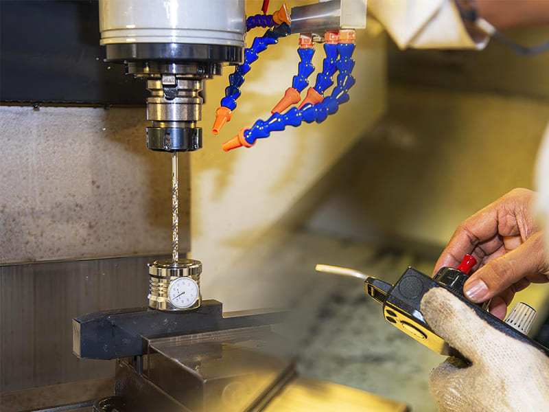
Quick Answer: Tool calibration is the process of comparing a measurement instrument against a traceable standard, documenting the deviation, and correcting (adjusting) the instrument if its error exceeds the allowable tolerance. Calibration is not the same as adjustment — a tool can be calibrated without adjustment if it is already within tolerance; the calibration record documents that fact. In manufacturing, calibration is required by ISO 9001 (general quality), IATF 16949 (automotive), and ISO 13485 (medical) as a foundation for process control, process capability (Cp/Cpk) measurement, and audit compliance. Without calibrated measurement systems, tolerance specifications on engineering drawings are unenforceable — you cannot verify what you cannot accurately measure.
What Is Tool Calibration?
Tool calibration is a controlled, documented comparison of a measurement instrument’s output against a measurement standard whose own accuracy is traceable to a national or international metrological authority (NIST in the United States, PTB in Germany, NPL in the United Kingdom). The process quantifies the instrument’s error and uncertainty at the time of calibration, documents this information on a calibration certificate, and determines whether the instrument’s performance is acceptable for its intended use.
The calibration process has three possible outcomes:
- Within tolerance — accepted: The instrument’s deviation from the standard is within the defined acceptable limit. The instrument is documented as calibrated and returned to service.
- Out of tolerance — adjusted: The instrument is physically or electronically corrected to reduce its error to within the acceptable limit, re-measured, and documented.
- Out of tolerance — condemned: The instrument cannot be corrected to within tolerance, is removed from service, tagged “DO NOT USE,” and replaced.
A fundamental distinction that is frequently misunderstood: calibration is the measurement and documentation process; adjustment is the corrective action that may or may not follow. An instrument can be fully, properly calibrated without any adjustment occurring. A calibration certificate documents the as-found condition (before adjustment), whether adjustment was performed, and the as-left condition (after adjustment, if applicable).
Traceability Chain
The credibility of any calibration result depends on an unbroken chain of traceability — each calibration standard used must itself be calibrated against a higher-order standard, with that chain ultimately linking to a national metrological standard (and through international mutual recognition agreements, to the SI unit definitions).
A practical traceability chain for a shop-floor micrometer:
- SI unit (meter, defined by the speed of light)
- National metrology institute (NIST, PTB — primary standard calibration)
- Accredited calibration laboratory (ISO/IEC 17025 accredited — secondary standard calibration)
- Manufacturer’s reference standards (gauge blocks calibrated by accredited lab)
- Shop-floor micrometer (calibrated against reference gauge blocks)
If any link in this chain is missing or unaccredited, the calibration cannot be considered traceable — and cannot satisfy ISO 9001, IATF 16949, or ISO 13485 requirements.
Why Calibration Matters in Precision Manufacturing
The Measurement Error Cascade
Measurement errors in manufacturing are not isolated events — they cascade through the production and inspection process in ways that create systematic quality failures.
Scenario A: Instrument reads low (measures parts as smaller than they actually are)
- Parts that are actually at the high end of the tolerance band are measured as within tolerance
- Parts that are actually slightly above the upper tolerance limit are measured as conforming
- Nonconforming parts are accepted → shipped to customer → assembly failures in service
Scenario B: Instrument reads high (measures parts as larger than they actually are)
- Parts that are actually within tolerance are measured as out of tolerance
- Conforming parts are rejected → increased scrap and rework cost
- Process adjusted incorrectly based on false data → good process disturbed, creating real problems
Both failure modes are economically harmful. The systematic nature of calibration errors — the same error applied consistently to every measurement — means that the problem grows with production volume. A 0.02 mm micrometer reading error applied to 10,000 parts per month is not a 0.02 mm problem; it is a quality risk affecting 10,000 decisions per month.
Process capability impact: Cp and Cpk values calculated from measurement data are only meaningful if the measurement system itself is capable and unbiased. The AIAG Measurement System Analysis (MSA) methodology quantifies measurement system capability through Gauge R&R studies — measuring the repeatability (same operator, repeated measurements) and reproducibility (different operators, same parts) components of measurement variation. A measurement system where gauge variation exceeds 10% of the tolerance band is considered marginally acceptable; above 30%, the measurement system is not adequate and process capability data is unreliable. Calibration is the foundation that makes Gauge R&R studies meaningful.
The Cost-Quality Connection
The economic argument for calibration is straightforward but frequently underestimated. Consider a precision aerospace machining operation producing $800 components with ±0.010 mm bore tolerance:
- Annual calibration cost for the bore gauge: $400–$600
- A single batch of 100 nonconforming parts shipped due to an uncalibrated gauge: $80,000 in customer returns, re-inspection, rework, and expedited replacement
- The calibration cost is approximately 0.5–0.75% of the cost of a single nonconformance event
The ratio is even more extreme for high-value assemblies where a dimensional error propagates to assembly failure — the cost of disassembling, scrapping, and replacing components in an assembled system can be 10–100× the cost of the individual part.
Calibration vs Verification vs Validation
These three terms describe related but distinct quality activities, and confusion between them leads to compliance failures and false confidence in measurement systems.
Calibration
What it does: Compares a measurement instrument against a traceable standard, quantifies the error and uncertainty, and documents the results. May or may not include adjustment, depending on whether the as-found condition is within tolerance.
Output: Calibration certificate with as-found and as-left data, uncertainty statement, traceability reference, calibration date, and next calibration due date.
Who does it: Typically performed by an accredited calibration laboratory (ISO/IEC 17025) or an internal calibration function with documented traceability.
Frequency: According to a defined calibration schedule based on instrument type, usage, and risk.
Verification
What it does: Checks whether a measurement instrument meets its required performance specification at a specific moment — typically a daily or per-shift check before use. Verification does not produce a calibration certificate and is not a substitute for calibration.
Output: Pass/fail determination. If the instrument fails verification, it is removed from service and sent for calibration.
Practical example: A machinist checks a micrometer against a certified gauge block before the morning production shift. If the reading is within the expected tolerance, the micrometer passes verification and is used. This verification does not replace the scheduled annual calibration.
Who does it: Operator or inspector at the point of use, following a documented verification procedure.
Validation
What it does: Confirms that a measurement system, inspection process, or production process produces results that fulfill the intended purpose — not just that individual instruments are accurate, but that the complete system works correctly end to end.
Output: System-level approval documentation. In medical device manufacturing, validation of an inspection process must demonstrate that the process reliably detects all nonconformances above a defined threshold. In automotive, measurement system validation includes Gauge R&R studies demonstrating adequate capability.
Who does it: Quality engineering, using a planned validation protocol.
Comparison Summary
| Aspect | Calibration | Verification | Validation |
|---|---|---|---|
| Scope | Individual instrument | Instrument readiness check | Complete system |
| Adjustment performed | Yes (if needed) | No | No |
| Output | Certificate with data | Pass/fail | System approval |
| Traceability required | Yes | References calibrated standards | Yes |
| Frequency | Scheduled intervals | Daily/per-shift | Project milestones |
| Performed by | Calibration lab / QE | Operator | Quality engineering |
Types of Instruments That Require Calibration
In manufacturing, any instrument that influences quality decisions — acceptance or rejection of product, process adjustment, or certification — must be calibrated. The scope extends beyond simple dimensional measuring tools.
Dimensional Measuring Instruments
The most common category in precision machining:
- Micrometers (OD, ID, depth): Calibrated against gauge blocks (end standards). Typical calibration points: zero, nominal range at multiple points through the measuring range.
- Calipers (vernier, digital, dial): Lower precision than micrometers; calibrated against gauge blocks or calibrated standards.
- Dial indicators and comparators: Calibrated against gauge blocks at multiple points through the measurement range; stylus condition and anvil parallelism verified.
- Gauge blocks (end standards): Grade-specific dimensional standards; themselves calibrated by an accredited laboratory against higher-grade reference standards.
- Plug gauges (GO/NO-GO): Calibrated for diameter, cylindricity, and surface finish at defined intervals; wear verification at each use.
- Ring gauges (setting rings, plain ring gauges): Calibrated for bore diameter and form.
- Height gauges: Calibrated at multiple heights through the measuring range.
- Bore gauges and internal measuring systems: Calibrated using setting rings of known diameter.
Coordinate Measuring Machines (CMM)
CMMs are complex multi-axis measurement systems whose calibration encompasses:
- Volumetric accuracy: Measured using calibrated artifact or laser tracker across the machine’s full work volume
- Probe calibration: Probe stylus tip radius compensation calibrated using a certified reference sphere
- Temperature compensation: CMM systems in thermally controlled environments perform continuous temperature monitoring for dimensional compensation
CMM calibration is typically performed by the manufacturer’s service organization or a specialized metrology service, following ISO 10360 standards (geometric performance requirements and testing of CMMs).
CNC Machine Tool Calibration
CNC machining centers have axis positioning accuracy that directly determines part dimensional accuracy. Machine tool calibration includes:
- Linear positioning accuracy (per ISO 230-2): Laser interferometer measurement of actual versus commanded axis positions at multiple points through the full travel range
- Bidirectional repeatability: Approach from both directions; measures reversal error (backlash)
- Geometric accuracy: Squareness between axes, spindle runout, and tram (perpendicularity of spindle to table)
- Thermal compensation verification: Temperature coefficient compensation systems require periodic verification under representative thermal loading
Modern CNC machining centers have internal monitoring systems (Renishaw or equivalent touch probes for tool length and diameter measurement, spindle monitoring) that provide continuous drift monitoring between formal calibrations. However, internal monitoring does not substitute for independent calibration — the monitoring system itself is subject to drift and must be calibrated.
Testing and Material Verification Equipment
- Hardness testers (Rockwell, Vickers, Brinell): Calibrated using certified hardness test blocks at each hardness scale used. Calibration procedure per ASTM E18 (Rockwell), ASTM E384 (Vickers), ASTM E10 (Brinell).
- Surface roughness testers: Calibrated using certified reference specimens with known Ra/Rz values.
- Tension testing machines: Calibrated for load cell accuracy and crosshead displacement per ASTM E4.
- Torque wrenches and torque tools: Calibrated over the used torque range — critical for safety-critical fastening operations.
- Pressure gauges and transducers: Calibrated against a dead-weight tester or calibrated reference.
- Thermocouples and temperature measurement systems: Calibrated at fixed temperature points (ice point, boiling point, or calibration furnace reference points) per ASTM E220.
Calibration Standards and Regulatory Requirements
ISO 9001:2015 — Clause 7.1.5
ISO 9001 requires organizations to determine monitoring and measuring requirements, provide necessary resources, and maintain calibration with traceability. Specifically:
- All measuring equipment must be calibrated at specified intervals
- Calibration must be against measurement standards traceable to international or national standards
- Calibration status must be identified (calibration sticker or tag)
- Equipment found to be out of calibration during inspection must trigger an assessment of the validity of previous measurement results
- Calibration records must be retained
A calibration record that is missing traceability information, is past due, or covers a tool used for a critical measurement is a common ISO 9001 audit finding. The corrective action typically requires re-inspection of product measured with the out-of-calibration instrument.
IATF 16949:2016 — Automotive Supplement
IATF 16949 adds requirements beyond ISO 9001 for automotive manufacturers:
- Customer-specific requirements for measurement system analysis (Gauge R&R studies per AIAG MSA manual)
- Calibration records must include calibration date, results, acceptance criteria, and next calibration date
- Calibration laboratory requirements: external labs must be accredited to ISO/IEC 17025 or equivalent
- Monitoring of measurement systems using control charts (stability monitoring)
- Internal calibration functions must satisfy specific requirements for personnel competence, traceability, and environmental control
ISO 13485:2016 — Medical Devices
ISO 13485 for medical device manufacturers requires:
- Risk-based calibration management — calibration requirements linked to the risk impact of measurement failures
- Calibration records maintained as part of the device history record (DHR)
- Specific requirements for environmental conditions during calibration
- Calibration recall procedure: when an instrument is found out of calibration, documented investigation of impact on previously inspected devices and, if necessary, notification to customers
ISO/IEC 17025:2017 — Calibration Laboratory Competence
ISO/IEC 17025 defines requirements for calibration laboratory competence, including:
- Technical competence of calibration personnel
- Measurement uncertainty estimation and reporting
- Environmental conditions for calibration
- Metrological traceability of measurement standards
- Laboratory impartiality and management requirements
When a manufacturing company uses an external calibration service, the service should be ISO/IEC 17025 accredited for the specific measurement parameters being calibrated. Accreditation scope matters — a lab accredited for dimensional calibration is not automatically accredited for hardness testing or electrical calibration.
Calibration Frequency: Risk-Based Approach
Fixed calibration intervals (e.g., “all tools calibrated annually”) are simple to administer but neither optimal nor consistent with modern quality standards. A risk-based calibration frequency model is more accurate and more economical.
Factors Determining Calibration Frequency
Usage intensity: An instrument used 8 hours per day, 5 days per week experiences far more mechanical stress, wear, and thermal cycling than one used occasionally. High-use instruments should be calibrated more frequently.
Environmental conditions: Temperature variation, humidity, vibration, and contamination all affect measurement instrument stability. Floor-level instruments in a production environment experience more adverse conditions than laboratory instruments in a controlled 20°C environment.
Precision of measurement relative to tolerance: An instrument used to measure a ±0.010 mm tolerance bore must be calibrated more frequently than one used to measure a ±0.5 mm position. The ratio of measurement instrument tolerance to product tolerance (the “test accuracy ratio” or TAR) defines how much margin exists for instrument error — a smaller TAR requires more frequent calibration to maintain adequate margin.
Historical calibration data: An instrument that consistently shows minimal drift over multiple calibration cycles can typically have its interval extended. An instrument that repeatedly requires adjustment at calibration should have its interval shortened. This data-driven adjustment of calibration frequency is both cost-optimal and technically appropriate.
Criticality of the measurement: Measurements used to accept or release product, to certify material properties, or to demonstrate process capability have higher stakes than measurements used only for process monitoring. Higher criticality warrants shorter intervals.
Recommended Calibration Frequency by Instrument Class
| Instrument Type | Usage Category | Suggested Interval |
|---|---|---|
| CMM (production environment) | High — daily use | 6–12 months (formal); monthly verification |
| Precision bore gauges | High — continuous use | 3–6 months |
| Micrometers (floor use) | Medium–high | 6 months |
| Calipers (floor use) | High | 3–6 months |
| Dial indicators (floor use) | Medium | 6 months |
| Gauge blocks (reference) | Low — protected storage | 12–24 months |
| Hardness tester | Medium | 6–12 months |
| Torque wrenches (safety-critical) | High | 3–6 months or per use |
| Temperature sensors (heat treatment) | Continuous | 6–12 months |
Note: These are starting point guidelines. Actual intervals should be adjusted based on the historical drift data from calibration records for the specific instrument and environment.
Calibration in CNC Machining: Integrated Measurement Control
Calibration in a CNC machining environment encompasses three interconnected systems — the CNC machine’s positioning accuracy, the cutting tool measurement system, and the inspection gauges used to verify finished parts. All three must be calibrated for the dimensional control chain to be complete.
Machine Tool Positioning Accuracy
Axis positioning accuracy drift in CNC machining centers occurs from:
- Mechanical wear (ballscrew wear, linear guideway wear)
- Thermal expansion from machine warm-up (axis growth of 0.01–0.05 mm over 1–2 hours is typical in machines without thermal compensation)
- Servo system parameter drift
Laser interferometer calibration per ISO 230-2 at scheduled intervals (typically 6–12 months for production machines) identifies positioning accuracy degradation before it affects product. Machine warm-up protocols and thermal compensation systems reduce thermal drift for production use between calibrations.
Cutting Tool Measurement
Tool length and diameter at the point of use must be accurately characterized for tight-tolerance CNC work. Methods:
- Tool presetter (offline): Tool length and diameter measured before mounting in the machine, with offset data loaded into the CNC controller. Tool presetters require calibration against traceable standards.
- On-machine probing (in-process): Touch probe cycles (Renishaw, Blum, and equivalent systems) measure tool length and diameter while installed in the spindle. The probe system itself requires calibration.
For sub-±0.02 mm tolerance work, in-process gauging (probing the workpiece after machining critical features) provides closed-loop correction that compensates for both machine drift and tool wear — the most reliable approach for consistent precision part production.
Inspection Gauging Integration
The output of a calibrated CNC machine is verified by calibrated inspection equipment. The full measurement chain requires:
- CNC machine calibrated (positioning accuracy known)
- Cutting tools measured (offset errors compensated)
- In-process gauging calibrated (real-time dimensional feedback)
- Final inspection gauging calibrated (conformance determination)
A deficiency at any point in this chain breaks the traceability of the final measurement result. For precision components (±0.005 mm or tighter), all four elements must be managed simultaneously.
Setting an Effective Calibration Strategy
An effective calibration strategy balances accuracy requirements against cost and operational complexity. The following framework provides a systematic approach.
Step 1: Classify Instruments by Risk
Assign each instrument to a risk category based on:
- The tolerance of the measurements it supports (tight = higher risk)
- The consequence of an undetected measurement error (safety-critical = highest risk)
- The frequency of use
Class A (Critical): Direct product acceptance/rejection; safety-critical measurements; tight-tolerance applications Class B (Important): Process monitoring; medium-tolerance measurements; non-safety-critical Class C (Standard): General reference; loose tolerance; process indicators
Step 2: Set Initial Calibration Intervals by Class
- Class A: 1–3 months; daily or shift verification
- Class B: 3–6 months; weekly verification
- Class C: 6–12 months; no formal verification required
Step 3: Adjust Based on Historical Data
After 2–3 calibration cycles, review the as-found data for each instrument:
- Instruments consistently found within tolerance with minimal drift → extend interval by 25%
- Instruments frequently found out of tolerance or at the edge of tolerance → shorten interval by 25%
This data-driven adjustment is both more accurate than fixed schedules and more economical — reducing unnecessary calibration of stable instruments and preventing failures from instruments with higher-than-expected drift rates.
Step 4: Implement Verification for Critical Instruments
For Class A instruments, daily or per-shift verification (comparison against a known reference artifact or gauge block) provides early warning of instrument problems between formal calibration cycles. The verification result is logged. If a verification fails, the instrument is removed from service and sent for formal calibration before measurements it made since the last successful verification are evaluated for impact on accepted product.
Key Takeaways
- Calibration is the foundation of measurement reliability — without traceable, documented calibration, tolerance specifications on engineering drawings cannot be enforced, process capability data is unreliable, and quality audit compliance cannot be demonstrated.
- Calibration and adjustment are not the same: calibration is the measurement and documentation process; adjustment is the corrective action that may follow. An instrument can be properly calibrated without adjustment if it is already within tolerance.
- Traceability is required for all quality system compliance (ISO 9001, IATF 16949, ISO 13485): the calibration certificate must identify the standard used, the accredited laboratory, and the measurement uncertainty — not just the as-found and as-left readings.
- Calibration frequency should be risk-based, not fixed: high-use, high-precision, safety-critical instruments need shorter intervals; adjust based on historical drift data from calibration records.
- In CNC machining, calibration is a three-layer system: machine positioning accuracy, cutting tool measurement, and inspection gauging — all three must be controlled for dimensional traceability to be complete.
- The cost of calibration is orders of magnitude lower than the cost of an undetected measurement failure: a single nonconforming batch from an uncalibrated gauge routinely exceeds annual calibration cost for that instrument.
- For OEM procurement teams: supplier calibration capability should be evaluated in supplier qualification and verified during audits — key questions include ISO/IEC 17025 accredited calibration lab usage, calibration interval documentation, Gauge R&R study results for critical measurements, and the procedure for handling out-of-calibration findings.
Frequently Asked Questions
What is tool calibration in manufacturing?
Tool calibration in manufacturing is the controlled, documented comparison of a measurement instrument against a traceable standard to determine the instrument’s accuracy, record its deviation, and adjust it if the deviation exceeds the allowable tolerance. Calibration applies to dimensional measuring tools (micrometers, calipers, CMMs), process control instruments (temperature sensors, pressure gauges, torque tools), and testing equipment (hardness testers, tensile machines). It is required by quality management standards including ISO 9001, IATF 16949, and ISO 13485 as a fundamental component of measurement control — without calibrated instruments, tolerance specifications cannot be verified, process capability (Cp/Cpk) data is unreliable, and quality audit compliance cannot be demonstrated.
How often should measurement tools be calibrated?
Calibration frequency should be risk-based rather than fixed. Typical guidelines: high-use, precision instruments (bore gauges, micrometers used for critical tolerance verification) should be calibrated every 3–6 months; general-purpose instruments (calipers, dial indicators) every 6 months; low-use reference standards (gauge blocks) every 12–24 months. Actual intervals should be adjusted based on historical calibration data — instruments that consistently show minimal drift can have intervals extended; instruments that frequently require adjustment should be calibrated more often. Critical safety-related instruments (torque tools on safety-critical fasteners, temperature sensors in heat treatment) may require calibration every 1–3 months or after each use.
What is the difference between calibration and verification?
Calibration is a formal, documented comparison of a measurement instrument against a traceable standard that produces a calibration certificate with quantified deviation, uncertainty, and traceability data. It may include physical adjustment if the instrument is out of tolerance. Verification is an informal check — comparing the instrument against a reference artifact before use (e.g., checking a micrometer against a gauge block at the start of a production shift) to confirm it is still performing within expectations. Verification produces a pass/fail result, not a calibration certificate. Verification is performed frequently (daily or per shift) as an operational safeguard between scheduled calibrations; it does not replace or extend calibration intervals.
What standards govern tool calibration?
The primary standards are: ISO 9001:2015 (Clause 7.1.5) — requires calibration of all monitoring and measuring equipment with traceability to national standards, documented records, and defined intervals; ISO/IEC 17025:2017 — defines requirements for calibration laboratory competence, including measurement uncertainty estimation, traceability, and personnel qualifications; IATF 16949:2016 — automotive supplement requiring Gauge R&R studies (per AIAG MSA), external lab accreditation to ISO/IEC 17025, and calibration control charts; ISO 13485:2016 — medical device standard with risk-based calibration requirements, device history record (DHR) integration, and documented calibration recall procedures for out-of-tolerance findings. Additional application-specific standards include ASTM E18 (Rockwell hardness testing), ISO 230-2 (CMM and machine tool accuracy), and ASTM E4 (tension testing machine calibration).
What happens if a measurement tool is found out of calibration?
When a measurement instrument is found out of calibration (either at a scheduled calibration or during a verification check), a defined response procedure must be followed. The instrument is immediately removed from service and labeled “DO NOT USE — OUT OF CALIBRATION.” An investigation is required to determine the potential impact of measurements made with the out-of-calibration instrument since its last known good calibration — this typically involves reviewing production records to identify which lots were inspected with the instrument and assessing whether the magnitude of the calibration error could have caused nonconforming product to be accepted. If the risk assessment determines nonconforming product may have been released, affected customers must be notified and the product recalled or re-inspected. This process — called calibration recall — is a mandatory requirement under ISO 9001, IATF 16949, and ISO 13485, and its absence is a critical audit finding.
Written by the CMS engineering team with 15+ years of precision CNC machining experience under ISO 9001 and IATF 16949 quality systems, managing calibration programs for dimensional measuring instruments, CMMs, and machine tool calibration for automotive, aerospace, medical, and industrial OEM manufacturing applications. Technical references: ISO 9001:2015 (Quality Management Systems — Clause 7.1.5), ISO/IEC 17025:2017 (General Requirements for Calibration Laboratories), IATF 16949:2016 (Automotive Quality Management — Calibration and MSA), AIAG Measurement System Analysis (MSA) Manual 4th Edition, ISO 230-2 (Machine Tool Testing — Determination of Accuracy and Repeatability).
Sourcing Precision CNC Machined Components With Documented Calibration Control?
At CMS, we maintain a documented calibration program for all dimensional measuring instruments, CMMs, and CNC machine tools under ISO 9001 requirements, with ISO/IEC 17025 accredited external calibration laboratory. Every precision component is inspected with calibrated instruments, and calibration traceability documentation is available upon request for customer audits.
[Request a quality system overview and CNC machining quote →]


