
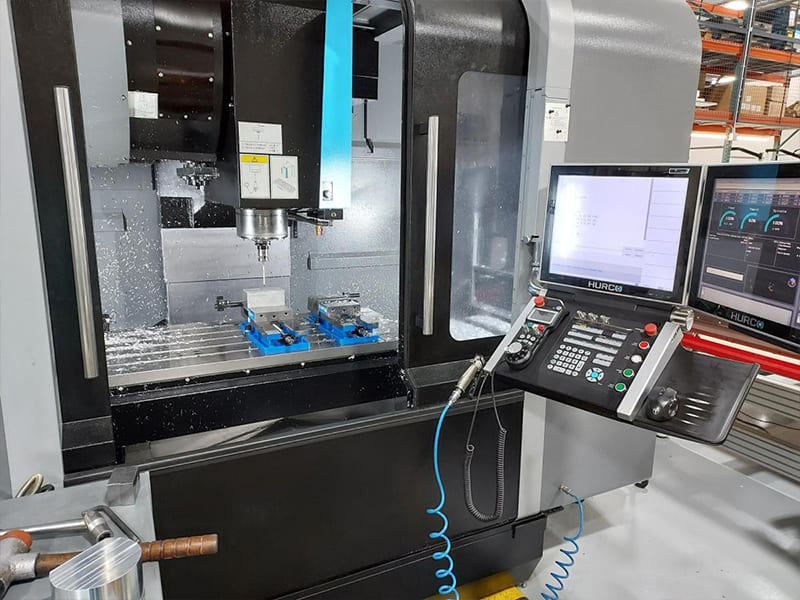
A machine shop quotes a 6-face aluminum housing requiring 4 separate setups on a 3-axis VMC — flip, re-clamp, re-indicate for each face. Total setup time: 45 minutes per part. Tolerance stack-up from repositioning produces ±0.05 mm between features on opposite faces. Moving to a 5-axis VMC machines all 6 faces in a single setup — setup time drops to 8 minutes, inter-face tolerance tightens to ±0.015 mm, and per-part cost drops 35%. The 5-axis machine costs 3× more per hour, but eliminating 3 setups more than compensates. We optimize VMC selection and setup strategy on CNC programs regularly. A vertical machining center (VMC) is a CNC milling platform with a vertically oriented spindle — tools approach the workpiece from above. It combines milling, drilling, tapping, and boring in one automated setup with automatic tool changing, making it the most widely used CNC platform for precision prismatic parts across virtually every manufacturing industry.
This guide covers how VMCs work, main components, types (3-axis through 5-axis), comparison with basic CNC mills and horizontal machining centers, suitable parts and materials, key specifications for selection, tooling systems, cost factors, advantages and limitations, and a practical decision framework.
How a VMC Works
A VMC coordinates three linear axes (X, Y, Z) with a rotating spindle under CNC control. The spindle holds and rotates cutting tools (end mills, drills, taps) at controlled speeds (typically 3,000–24,000+ RPM). The worktable moves in X (left-right) and Y (front-back) while the spindle moves in Z (up-down), positioning the tool precisely against the clamped workpiece.
Material removal happens as the rotating tool engages the workpiece along programmed toolpaths (G-code). Coolant reduces heat, extends tool life, and improves surface finish. An automatic tool changer (ATC) switches between tools — typically 16–60+ in the magazine — enabling multiple operations (face milling, pocketing, drilling, tapping, boring) in a single setup without manual intervention.
Precision capability: ±0.01 mm or better is standard on modern VMCs, with repeatability ensuring consistent dimensions across production batches. Based on our production data, our VMC programs achieve ±0.01 mm on approximately 90% of precision features in aluminum and steel — the remaining 10% requiring tighter tolerance use grinding or post-machining finishing.
Main Components
| Component | Function | Selection Impact |
|---|---|---|
| Spindle | Rotates tools (speed + torque) | Determines material capability and finish |
| Worktable | Supports workpiece/fixtures | Defines max part size and weight |
| ATC | Switches tools automatically | Affects cycle time and multi-op capability |
| CNC control | Executes G-code programs | Controls accuracy and programming efficiency |
| Tool holder (BT/CAT/HSK) | Connects tool to spindle | Affects rigidity and high-speed stability |
| Coolant system | Delivers coolant to cut zone | Improves tool life and chip evacuation |
Spindle
The performance core. Speed range determines material suitability: 8,000–12,000 RPM for general machining, 15,000–24,000+ RPM for high-speed aluminum work. Torque at lower RPM is critical for steel roughing — a high-RPM spindle without adequate torque struggles in heavy cuts. In our shop floor experience, matching spindle torque curve to the actual material mix matters more than maximum RPM specification — an aluminum-optimized 20,000 RPM spindle underperforms on stainless steel programs where 8,000 RPM with 2× the torque would be far more productive.
Tool Holders
BT/CAT (general purpose): Robust, widely available, cost-effective. Standard for general milling and drilling. HSK (high performance): Hollow shank with dual taper + face contact. Superior rigidity at high RPM, better runout control. Preferred for high-speed aluminum finishing and tight-tolerance work. Tool holder rigidity directly affects chatter, tool life, and achievable surface finish.
ATC Systems
Umbrella/carousel: Simple disk near spindle head. Lower cost, slower tool change, fewer tools. Suitable for simple parts. Side-mount arm type: Separate magazine with swing arm. Faster chip-to-chip time, 24–60+ tool capacity. Better for complex multi-operation parts and production environments.
Types of VMCs
| Type | Configuration | Best For | Trade-off |
|---|---|---|---|
| 3-axis | X, Y, Z | Plates, brackets, simple parts | Multiple setups for multi-face |
| 4-axis | X, Y, Z + rotary A | Cylindrical parts, side features | Limited complex angles |
| 3+2 axis | X, Y, Z + indexed rotation | Multi-face parts, angled features | No simultaneous contouring |
| Full 5-axis | Continuous X, Y, Z + A, B/C | Aerospace, impellers, freeform | Higher cost + programming |
3-axis is the baseline standard — most widely used, lowest cost, ideal for prismatic parts machined from one or two faces. 4-axis adds rotary indexing for cylindrical parts and side features without reclamping. 3+2 (positional 5-axis) positions the part at compound angles, then machines in 3 axes — dramatically reduces setups on multi-face parts. Full 5-axis enables simultaneous movement of all axes — required for complex freeform surfaces (impellers, turbine blades, aerodynamic components).
Selection logic: Simple flat parts → 3-axis. Parts needing rotation → 4-axis. Multi-face precision → 3+2. Complex freeform surfaces → full 5-axis. One common pitfall we see: specifying 5-axis for parts that only need 3+2 capability — full 5-axis adds programming complexity and machine cost without benefit when simultaneous contouring isn’t geometrically required.
VMC vs Basic CNC Mill
| Aspect | VMC | Basic CNC Mill |
|---|---|---|
| Automation | High (ATC, program-driven) | Lower (often manual tool change) |
| Tool change | Automatic (16–60+ tools) | Manual or semi-automatic |
| Multi-operation | Milling + drilling + tapping in one setup | Often requires multiple setups |
| Best for | Batch production, complex parts | Simple parts, prototyping |
All VMCs are CNC milling machines — but not all CNC mills are machining centers. The VMC adds automatic tool changing, enclosed machining area, and multi-operation capability that enables production-level throughput and consistency.
VMC vs Horizontal Machining Center (HMC)
| Factor | VMC | HMC |
|---|---|---|
| Spindle orientation | Vertical (top-down) | Horizontal (side approach) |
| Setup cost | Lower | Higher |
| Chip evacuation | Moderate (chips accumulate) | Better (gravity-assisted) |
| Multi-side machining | Requires re-fixturing or 4/5-axis | Strong (pallet + tombstone) |
| Automation | Standard | Often includes pallet changers |
| Best for | Low-medium volume, flexibility | High volume, multi-face parts |
VMC advantages: Lower equipment and setup cost. Better operator visibility and access. Faster setup changes for high-mix production. More compact footprint. HMC advantages: Superior chip evacuation (gravity clears chips). Better multi-face access with tombstone fixtures. Pallet changers enable near-continuous production. Higher spindle utilization in volume production. Based on our production data, VMCs handle approximately 80% of our CNC milling programs — the combination of flexibility, lower cost, and adequate precision covers the vast majority of prismatic part requirements. HMCs are justified primarily for high-volume multi-face production where pallet automation and chip management deliver measurable per-part cost advantage.
Parts and Materials
Typical Parts
| Industry | Parts | Why VMC |
|---|---|---|
| Automotive | Brackets, housings, fixtures | Fast multi-op machining |
| Aerospace | Structural plates, prototypes | High accuracy, aluminum expertise |
| Medical | Instrument parts, housings | Tight tolerances (±0.01 mm) |
| Electronics | Heat sinks, enclosures | Surface finish + thin-wall capability |
| Industrial | Base plates, adapters, blocks | Flexible operations in one setup |
VMCs excel at prismatic geometry — flat surfaces, pockets, slots, drilled/tapped hole patterns, and contoured profiles. Multi-operation capability (mill + drill + tap + bore) in single setup reduces alignment error and lead time.
Materials
| Material | VMC Suitability | Notes |
|---|---|---|
| Aluminum (6061/7075) | Excellent | High speed, great finish, lowest cost |
| Carbon steel (1045, 4140) | Good | Stable cutting, coated carbide tools |
| Stainless steel (304/316) | Good | Lower speeds, strong coolant needed |
| Titanium | Moderate | Low speed, high torque, strict heat control |
| Brass / Copper | Good | Soft, manage burrs |
| Engineering plastics | Good | Manage heat and clamping deformation |
Key Specifications
| Specification | Why It Matters |
|---|---|
| X/Y/Z travel | Maximum part envelope |
| Table size and load | Fixture capacity and max weight |
| Spindle speed (RPM) | Material capability (Al vs steel) |
| Spindle torque (Nm) | Roughing capability in hard materials |
| Tool magazine capacity | Multi-operation complexity |
| Taper type (BT/CAT/HSK) | Rigidity and speed capability |
| Positional accuracy | Achievable tolerances |
| Coolant (flood vs TSC) | Deep hole and heat-sensitive operations |
Specification matching rule: Match spindle speed to material mix (aluminum → high RPM, steel → high torque). Choose travel with 20–30% margin over largest parts. Select tool magazine size based on operation count per part. Through-spindle coolant (TSC) is essential for deep drilling and stainless/titanium work.
Cost Factors
| Driver | Impact |
|---|---|
| Material | Harder = slower = more expensive |
| Machining time | Primary cost driver |
| Setup count | More setups = higher labor + alignment cost |
| Tooling | Specialized tools increase cost |
| Tolerance / finish | Tighter = slower finishing passes |
| Batch size | Higher volume = lower per-part cost |
| Machine type | 5-axis costs more/hour but may reduce total |
Key cost insight: Machine hourly rate × cycle time + setup cost ÷ batch size = per-part cost. The cheapest machine per hour doesn’t always produce the cheapest parts — a 5-axis VMC at 2× the hourly rate that eliminates 3 setups often delivers lower per-part cost on complex multi-face components. In projects we’ve delivered, DFM-optimized parts (fewer setups, standard radii, realistic tolerances) consistently reduce VMC machining cost by 20–35% versus over-engineered designs.
Advantages and Limitations
| Advantages | Limitations |
|---|---|
| Flexible for prototypes and batches | Chip accumulation on workpiece |
| Lower setup and equipment cost | Multi-side parts need re-fixturing (3-axis) |
| Good operator visibility/access | Deep cavities challenge tool reach |
| Wide material compatibility | Lower automation than palletized HMC |
| Precision milling capability | Part height limited by spindle clearance |
Decision Guide
| Condition | Recommendation |
|---|---|
| Prismatic parts (plates, brackets) | VMC (3-axis) |
| Prototype / low volume | VMC |
| Multi-face features | 4-axis or 5-axis VMC |
| High-volume multi-face production | Compare HMC |
| Deep cavity / chip concerns | Optimize VMC coolant or consider HMC |
| Complex freeform surfaces | Full 5-axis VMC |
| Cost-sensitive, standard geometry | 3-axis VMC with DFM optimization |
DFM Tips
Control pocket depth: Deep cavities require long tools → vibration, slower cutting, higher cost. Keep depth-to-width ratio ≤4:1 where possible. Use standard radii: Match internal corner radii to standard end mill sizes (R3, R5). Sharp internal corners require slow machining or EDM. Minimize setups: Align features for machining from one or two faces. Fewer setups = better accuracy + lower cost. Manage thin walls: Avoid walls below 1.0–1.5 mm unless function requires it — thin features deform under cutting forces. Specify realistic tolerances: ±0.05 mm for general features, ±0.01 mm only where fit or function demands it. Over-tolerancing increases finishing time and inspection cost without functional benefit.
Conclusion
The vertical machining center is the most versatile and widely used CNC platform for precision prismatic parts — combining milling, drilling, tapping, and boring in automated single-setup operation. From 3-axis for simple brackets to full 5-axis for aerospace freeform surfaces, VMC configurations scale to match part complexity and production volume.
Cost is driven by cycle time, setup count, material, and tolerance — not just machine type. DFM optimization (standard radii, controlled pocket depth, realistic tolerances, minimized setups) delivers 20–35% cost reduction on typical programs. For most precision CNC parts at low-to-medium volumes, a properly selected VMC provides the optimal balance of accuracy, flexibility, and cost efficiency. Need help selecting the right VMC configuration or optimizing your parts for VMC machining? [Contact our engineering team] for DFM review, process planning, and manufacturing support.
FAQ
What is a vertical machining center?
A CNC milling platform with a vertical spindle — tools approach the workpiece from above. Combines milling, drilling, tapping, and boring with automatic tool changing in a single automated setup. The most widely used CNC platform for precision prismatic parts.
VMC vs HMC — which should I choose?
VMC for flexibility, lower cost, and low-to-medium volume production. HMC for high-volume multi-face production with pallet automation and superior chip evacuation. VMCs handle ~80% of typical CNC milling work.
What parts can a VMC make?
Brackets, housings, plates, fixtures, molds, heat sinks, medical components, and any prismatic geometry with pockets, holes, and flat surfaces. Works across aluminum, steel, stainless, titanium, and engineering plastics.
3-axis vs 5-axis — when does 5-axis make sense?
When the part has features on multiple faces requiring tight inter-face tolerance, or complex freeform surfaces. 5-axis eliminates setups and improves accuracy. For simple flat parts, 3-axis is more cost-effective. Don’t specify 5-axis when 3+2 positioning achieves the same result.
How to reduce VMC machining cost?
Minimize setups (design for single-face access). Use standard internal radii. Control pocket depth. Specify tight tolerances only on functional features. Choose appropriate material (aluminum machines 2–3× faster than stainless). DFM review before production typically saves 20–35%.


