
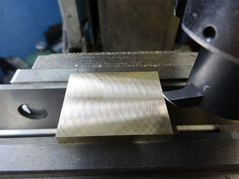
A prototype shop needs Ra 0.6 µm on a 200 × 150 mm aluminum 6061-T6 fixture plate. The 50 mm face mill with 5 indexable inserts produces Ra 1.4 µm — two inserts sitting 0.015 mm higher than the others create a visible repeating pattern across the surface. Switching to a single-point fly cutter at the same feed rate drops Ra to 0.5 µm in one pass. No insert height variation, no multi-edge patterning — just one cutting edge producing one consistent scallop per revolution. We run this comparison regularly on prototype and fixture plate work. A fly cutter’s single-point geometry eliminates the insert-to-insert variation that multi-tooth face mills can’t fully escape — producing smoother, more uniform flat surfaces on aluminum at lower tooling cost than any indexable alternative.
A fly cutter is a single-point or two-point rotating milling tool designed for flat surface finishing. This guide covers how fly cutters work, which types suit which applications, cutting parameter setup, material compatibility, tool geometry, chatter prevention, CAM programming, and when to choose a fly cutter versus a face mill.
How a Fly Cutter Works
One or two cutting edges mount on an adjustable arm, sweeping across the workpiece in a wide circular arc. Each revolution produces one scallop from one edge at one consistent geometry.
| Feature | Fly Cutter | End Mill | Face Mill |
|---|---|---|---|
| Edges | Single or two | Multiple flutes | Multiple inserts |
| Cutting action | Periodic single-point | Continuous multi-point | Continuous multi-point |
| Surface formation | One consistent scallop/rev | Tool marks along path | Insert pattern possible |
| Adjustability | Arm position adjustable | Fixed geometry | Fixed insert geometry |
| Primary use | Large flat finishing | Contours, pockets | High-volume facing |
The Scallop Pattern
Every revolution leaves a shallow cusp. With a face mill, multiple inserts at slightly different heights create inconsistent overlapping scallops. With a fly cutter, one edge produces one scallop per revolution at consistent depth. Feed rate and cutter radius together determine scallop height:
Scallop Height ≈ f² / (8 × r) (f = feed/rev, r = nose radius)
Keep feed low and radius large → scallop height drops to where surface roughness becomes a function of edge geometry rather than kinematics. Based on our production data, a well-tuned fly cutter on 6061-T6 achieves Ra 0.4–0.8 µm in a single finishing pass.
Types of Fly Cutters
| Type | Features | Best Application |
|---|---|---|
| Single-point | Simple, predictable | Aluminum fixtures, prototypes |
| Two-insert | Better balance, higher MRR | Larger surfaces, medium alloys |
| Adjustable arm | Flexible radius | Development work, custom finishes |
| Indexable | Repeatable insert geometry | Repeat production, fast changeover |
| Helical / special | Reduced chatter, smoother entry | Thin plates, high-speed finishing |
Single-point: One edge. Simplest setup, most predictable scallop behavior. Right for aluminum finishing and lighter machines where spindle rigidity limits two-insert designs.
Two-insert: Better balance and MRR — but only when both inserts match within 0.01 mm height. Even 0.02 mm mismatch reintroduces the variation that defeats the purpose of fly cutting. In our shop floor experience, two-insert designs reward careful setup and penalize shortcuts.
Adjustable arm: Repositionable blade for specific scallop heights and part widths. Useful for development. Trade-off: requires height verification before each run.
Indexable: Insert swap restores geometry without adjustment. For production environments running the same operation repeatedly — reduces cycle-to-cycle variation.
Helical: Angled cutting edge distributes entry impact over a longer engagement arc. Reduces chatter on thin-wall parts and high-speed aluminum finishing.
Fly Cutter vs. Face Mill
| Factor | Fly Cutter | Face Mill |
|---|---|---|
| Surface finish | Excellent — no insert variation | Good — dependent on insert consistency |
| MRR | Low–moderate | High |
| Tooling cost | Low | Higher |
| Machine power | Low — suits lighter mills | Higher — needs rigid spindles |
| Process flexibility | High | Lower |
When Fly Cutter Wins
Surface quality on aluminum. On 6061-T6 fixture plates, prototype parts, and finish-critical flat surfaces, single-point geometry outperforms multi-insert tooling consistently. Also works well on machines with limited spindle power where large face mills would chatter.
For low-volume work, cost reinforces the technical case — a fly cutter body with HSS or carbide inserts costs a fraction of a comparable indexable face mill.
When Face Mill Is Better
High-volume production, hard materials, and roughing. The intermittent single-point impact that produces smooth finish on aluminum becomes a liability on steel at aggressive parameters — concentrating forces, accelerating wear, and driving chatter. When throughput matters and finish targets are achievable with a face mill, use the face mill.
Cutting Parameters
With one edge, every parameter maps directly to the surface — no multi-edge averaging. Getting parameters right is critical.
Spindle Speed
RPM = (SFM × 12) / (π × Effective Diameter)
Calculate from the full swing diameter, not the shank. A 100 mm swing on 6061-T6 at 800 SFM ≈ 764 RPM — more conservative than expected. Overspeeding increases imbalance effects and edge wear without improving finish.
Feed Rate
Feed per revolution is the primary surface quality lever. Lower feed = shallower scallops = smoother finish. The relationship is direct and predictable with a single edge. Start very low and increase while monitoring texture.
Depth of Cut
Fly cutters are finishing tools. Deep cuts increase impact loading, stress bearings, and degrade finish. Almost always adjusted toward shallower.
| Material | SFM | Feed/Rev | DOC |
|---|---|---|---|
| Aluminum 6061 | 600–1,000 | 0.02–0.05 mm/rev | 0.05–0.25 mm |
| Carbon steel | 200–350 | 0.01–0.03 mm/rev | 0.05–0.15 mm |
| Stainless 316L | 150–250 | 0.01–0.02 mm/rev | 0.03–0.10 mm |
Adjust feed first if finish isn’t satisfactory — before changing RPM or DOC. Verify balance before every run. Make a test pass before committing to the full surface.
Material Compatibility
| Material | Suitability | Rationale |
|---|---|---|
| Aluminum 6061/7075 | ★★★★★ Excellent | Low resistance, stable chips, high conductivity |
| Carbon / low-alloy steel | ★★★☆☆ Conditional | Feasible for light finishing with rigid setup |
| Stainless 316L | ★★☆☆☆ Limited | Work hardening adds force variability |
| Cast iron / hard alloys | ★☆☆☆☆ Not recommended | Abrasive, impact spikes |
Aluminum is the natural fit. Low shear strength keeps forces manageable even on moderate spindles. Chips form cleanly. Edge geometry stays consistent pass to pass — producing repeatable Ra values. On 7075-T6 (higher hardness), reduce feed 15–20% versus 6061 for equivalent finish.
316L stainless: Possible but not preferred. Work hardening occurs if the edge rubs rather than cuts. If necessary: sharp carbide, positive rake, no dwelling, DOC ≤ 0.08 mm. One common pitfall we see: attempting fly cutting on stainless with the same parameters used for aluminum — immediate work hardening and degraded finish.
Tool Geometry
Rake Angle
Positive rake (+5° to +15°) for aluminum — reduces force, improves chip flow, produces clean finish. Neutral to slightly negative (0° to −5°) for steel — adds edge strength but raises chatter risk. Higher rake = better finish but shorter edge life.
Relief Angle
Prevents flank rubbing on the freshly cut surface. Too little → heat buildup, surface smearing. Too much → fragile edge, chipping under impact. Standard: 6°–10° (lower for steel, higher for aluminum).
Nose Radius
Directly determines scallop height: Scallop ≈ f² / (8r). Larger radius → lower scallop at same feed. 0.4–1.0 mm for mirror finishes. Trade-off: larger radius increases radial force → higher machine rigidity requirement.
HSS vs. Carbide
HSS: Sharper edges, higher positive rake, better impact tolerance. Advantage on lightweight machines and aluminum finishing. Limited wear resistance. Carbide: Better wear resistance but blunter geometry increases forces. On light CNC mills, carbide fly cutters can drive chatter that HSS at the same parameters would avoid.
Chatter Prevention
Chatter is the most common fly cutter failure mode — and the reason shops abandon the tool. Intermittent single-point engagement amplifies any setup compliance, imbalance, or resonance.
Systematic approach (in order):
- Minimize tool overhang — every mm of stick-out multiplies deflection
- Maximize workholding contact — full surface on a flat fixture; avoid cantilevers. For thin aluminum plates, double-sided tape on precision granite is standard prototype practice
- Verify tool balance after every insert change or arm adjustment
- Reduce feed per revolution first — lowers impact load
- Reduce DOC second — reduces force per engagement
- Adjust RPM third — shift ±10% to move away from resonance
- Use climb milling — smoother entry reduces impact versus conventional
For mirror-level finishes: Prioritize low feed over high RPM. Two light passes beat one heavier pass. Test 50 mm before committing to the full surface.
CAM Programming
Define Effective Diameter
Enter the full swing diameter in the tool library, not the shank. Wrong diameter → incorrect surface speed calculation → meaningless RPM and finish simulation. Also define nose radius explicitly for scallop height calculation.
Toolpath Strategy
Stepover: Large relative to effective diameter — fly cutters cover wide areas efficiently. Direction: Climb mill for smoother entry. Entry: Gentle lead-ins, not direct plunges — the single edge takes full impact alone. Z-depth: Constant throughout the pass — variable depth causes variable force and inconsistent finish.
CAM checklist: Confirm RPM from effective diameter. Set stepover to match finish target. Program consistent parallel passes. Simulate scallop height before running.
Safety
Fly cutters deserve more attention than their simple construction suggests. Large swing diameter at speed generates substantial centrifugal force on an inherently asymmetric tool.
Key risks: High tip speed even at moderate RPM. Asymmetric mass generates rotating force increasing with RPM². Insert ejection risk if fastener torque is insufficient.
Protocol: Verify insert seating and fastener torque before every run. Confirm RPM within manufacturer’s rated speed for the swing diameter. Stand to the side during test passes. Stop immediately if unusual vibration develops.
Don’t use fly cutters for: Heavy roughing, interrupted cuts (pockets with steps), hard/abrasive materials, or unattended machining.
Conclusion
Fly cutters occupy a specific CNC role: precision flat-surface finishing on aluminum and non-ferrous alloys where surface quality matters more than throughput. Their single-point mechanism — sensitive to setup quality but capable of finishes that face mills struggle to match — produces Ra 0.4–0.8 µm on 6061-T6 when properly applied.
The practical takeaway: fly cutters reward engineering judgment and penalize shortcuts. Rigid setup, correct effective-diameter RPM, low feed per revolution, verified balance, and methodical tuning separate a mirror finish from a vibration-damaged surface. Need help selecting fly cutters or optimizing CNC surface finishing for your components? [Contact our engineering team] for tooling guidance and manufacturing support.
FAQ
Is a fly cutter better than a face mill for finish?
For aluminum finishing — often yes. Single-point eliminates insert height variation, achieving Ra 0.4–0.8 µm on 6061-T6. Trade-off: lower MRR and higher setup sensitivity. Face mills win on throughput and hard materials.
Can fly cutters be used on CNC?
Yes — most effective on CNC where feed and RPM are held precisely. Enter effective swing diameter (not shank) in CAM for correct speed calculation. Program consistent parallel passes with climb milling.
What RPM for a fly cutter?
Calculate from effective diameter: RPM = (SFM × 12) / (π × Diameter). For 6061-T6 at 800 SFM with 100 mm swing ≈ 764 RPM. Start conservative, verify finish on a test pass, adjust feed before RPM.
Why do fly cutters produce mirror finish?
One edge, one consistent geometry, one scallop per revolution. No insert height mismatch. Scallop height directly controlled by feed per revolution and nose radius. On 6061-T6 with positive rake, 0.4–0.8 mm nose radius, and feed below 0.03 mm/rev → uniform reflective surface.
Are fly cutters safe at high speed?
Within rated limits, yes. Large diameter + speed = high centrifugal force. Verify insert torque, confirm RPM within rated speed for swing radius, and stand clear during first passes. If imbalance vibration appears, stop immediately.


