
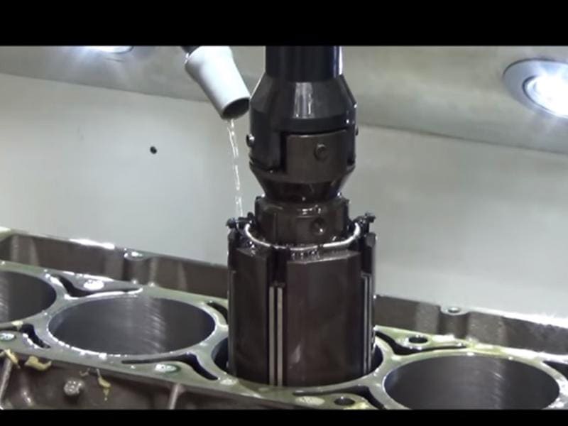
Quick Answer: Honing is a precision abrasive finishing process that removes 0.002–0.02 mm of material from internal cylindrical bores using multiple abrasive stones mounted on a rotating, reciprocating mandrel. The simultaneous rotational and axial motion corrects geometric errors (roundness, cylindricity, taper) and produces a cross-hatch surface pattern at 30°–60° that retains lubricating film. Achievable tolerances: ±0.001–0.010 mm diameter; surface roughness Ra 0.1–0.8 µm. Honing is the final precision step after rough boring and reaming — it does not shape holes, it finalizes their functional performance for sealing, lubrication, and wear resistance.
What Is the Honing Process?
Honing is a precision abrasive micro-finishing operation applied to internal cylindrical bore surfaces. A honing tool — a mandrel carrying multiple abrasive stones — expands radially against the bore wall under controlled pressure while simultaneously rotating and reciprocating along the bore axis. This combined kinematic motion removes a small, controlled amount of material and generates the characteristic cross-hatch groove pattern at controlled angles of 30°–60°.
What distinguishes honing from boring, reaming, or grinding is its purpose. Boring and reaming remove material to establish geometric position and size. Honing refines size from a pre-machined near-final dimension, corrects residual geometric errors — out-of-round, taper, barrel shape — and creates a functional surface texture that governs how the bore performs in service. The cross-hatch valleys retain lubricating film; the load-bearing plateaus support mating components; the controlled roughness governs sealing performance and break-in wear behavior.
For components where bore performance directly determines system reliability — engine cylinders, hydraulic actuators, pneumatic cylinders, precision gearboxes, and medical device components — honing is not an optional finishing step. It is the process that transforms a machined hole into a functional surface.
How the Honing Process Works
Abrasive Stone Expansion: Radial Pressure Control
The honing tool carries three to twelve abrasive stones arranged symmetrically around the mandrel body. The stones expand outward against the bore wall through a mechanical wedge, spring, or hydraulic actuator, applying controlled radial contact pressure. This pressure governs material removal rate and surface finish:
- Higher pressure: faster stock removal, greater geometry correction capability, but increased risk of surface tearing
- Lower pressure: slower removal, finer surface finish, better final geometry control
In practice, honing uses a step-down pressure strategy — moderate-to-high pressure for the initial sizing phase (correcting geometry and approaching target diameter), followed by a low-pressure finishing phase and a spark-out dwell (tool dwelling at position without advancing) to achieve the target Ra and final diameter.
Rotation and Reciprocation: The Cross-Hatch Mechanism
The defining kinematic feature of honing is the combination of:
- Spindle rotation (tool rotating about its axis): circumferential cutting velocity
- Reciprocating stroke (tool moving axially along the bore): full bore length coverage and helical groove formation
The intersection of these two motions generates the cross-hatch pattern. The angle relative to the bore axis is determined by the ratio of stroke velocity to rotational velocity:
- Higher stroke-to-rotation ratio: steeper cross-hatch angle (approaching 60°)
- Lower ratio: shallower angle (approaching 30°)
For engine cylinder applications, cross-hatch angles of 40°–50° are typical — providing sufficient oil retention capacity with adequate plateau area for load support.
Why the Cross-Hatch Pattern Matters
The cross-hatch surface is an engineered functional feature, not a surface defect:
Oil retention: The intersecting micro-valleys act as distributed lubricant reservoirs, replenishing oil film at the sliding contact interface during operation. A smooth bore surface would squeeze out the lubricant film under load, causing boundary lubrication and accelerated wear.
Controlled run-in: The load-bearing plateau regions carry initial contact load during break-in, while valleys maintain lubrication. As plateaus wear minimally during run-in, the surface stabilizes at its designed operating geometry.
Sealing performance: Controlled surface roughness Ra 0.1–0.4 µm with defined plateau and valley structure provides better sealing performance than either too-rough (high leakage paths) or too-smooth (lubricant starvation) surfaces.
Process Parameters and Their Effects
| Parameter | Primary Effect | Optimization Approach |
|---|---|---|
| Stone grit size | Ra and material removal rate | Coarse (80–150) for sizing; fine (320–600+) for finishing |
| Stone pressure | Removal rate vs finish quality | Step-down: high for sizing, low for finishing + spark-out |
| RPM vs stroke ratio | Cross-hatch angle | Set per application (typically 40°–50° for engines) |
| Stroke length | Full bore coverage, taper prevention | Cover 1/3 stone length past each bore end |
| Coolant | Surface integrity, chip evacuation | Clean filtered honing oil; consistent flow |
| Stock allowance | Geometry correction capability | 0.01–0.03 mm pre-hone allowance on diameter |
Honing Accuracy and Surface Finish
Dimensional Accuracy
Honing achieves diameter tolerances of ±0.001–0.010 mm with roundness and cylindricity correction to 1–5 µm:
What makes honing’s accuracy unique is the multiple-stone averaging effect. If one side of the bore is slightly larger, the stones on that side remove more material until equilibrium is reached — the stones inherently correct asymmetric geometry. This self-correcting mechanism is why honing can achieve roundness correction that single-point boring cannot match.
Final sizing is achieved through controlled material removal with in-process gauging (air gauging during the honing cycle) and spark-out passes at reduced pressure.
Surface Roughness
Achievable surface roughness by honing stage:
| Honing Stage | Abrasive Grit Range | Achievable Ra |
|---|---|---|
| Stock removal (coarse) | 80–150 grit | 1.0–2.5 µm |
| Semi-finish | 180–280 grit | 0.4–1.0 µm |
| Finish honing | 320–600 grit | 0.1–0.4 µm |
| Plateau honing | 600+ grit, low pressure | 0.05–0.2 µm |
For engine cylinders, the specification is not Ra alone but the Abbott-Firestone bearing ratio curve parameters — Rpk (reduced peak height), Rk (core roughness), Rvk (valley depth) — that characterize plateau height and valley depth separately. These parameters reflect that functional performance depends on the plateau-to-valley ratio, not just average roughness.
Functional Consequences of Surface Quality
Sealing performance: Improved bore geometry (roundness/cylindricity) combined with controlled Ra ensures uniform contact with seals or piston rings, reducing leakage in hydraulic cylinders, pneumatic systems, and engine bores.
Lubrication behavior: Cross-hatch valleys store oil and distribute it continuously during sliding motion, maintaining a stable lubricating film even under load.
Wear resistance: Plateau surface reduces initial high peaks (reducing run-in wear), while balanced texture minimizes metal-to-metal contact during steady-state operation.
Honing vs Grinding vs Reaming vs Lapping
Process Comparison
| Parameter | Honing | Internal Grinding | Reaming | Lapping |
|---|---|---|---|---|
| Primary application | Internal bore finishing | Internal/external surfaces | Bore sizing | Ultra-flat or precision surfaces |
| Material removal | 0.002–0.02 mm | 0.05–0.5 mm | 0.05–0.5 mm | < 0.002 mm |
| Achievable Ra | 0.1–0.8 µm | 0.2–1.6 µm | 0.4–3.2 µm | < 0.05 µm |
| Geometry correction | Excellent (roundness, cylindricity) | Good | Limited | Excellent (flatness) |
| Cross-hatch texture | Yes (functional) | No | No | No |
| Typical bore tolerance | ±0.001–0.010 mm | ±0.005–0.020 mm | ±0.010–0.050 mm | < ±0.001 mm |
When to Choose Each Process
Choose honing when: internal bore requires cross-hatch texture for lubrication or sealing; geometry correction (roundness, cylindricity, taper) is needed beyond preceding machining; tolerance ±0.001–0.010 mm; Ra 0.1–0.8 µm.
Choose internal grinding when: material is too hard for honing stones (>60 HRC without CBN tooling), larger stock removal (0.05–0.5 mm) is needed, or external/complex geometry is involved.
Choose reaming when: sizing to a close tolerance is the primary requirement, Ra 0.4–1.6 µm is acceptable, and cross-hatch texture is not functionally required. Reaming is a single-pass sizing operation, not a geometry correction process.
Choose lapping when: Ra below 0.05 µm is specified (optical components, precision valve seats), or flatness requirements are extreme — not typically applicable to cylindrical bores.
Types of Honing
Conventional Stroke Honing
Stroke honing uses a multi-pass process where the honing tool makes multiple reciprocating cycles through the bore, progressively removing material and correcting geometry. Stone pressure, RPM, stroke rate, and cycle time are adjusted to achieve target diameter, roundness, and Ra. This flexibility makes stroke honing suitable for bores with significant geometric errors, variable pre-machining quality, or stringent final specifications.
Best for: engine cylinders, hydraulic cylinders, aerospace components, repair operations where bore geometry is irregular.
Single-Pass Honing
Single-pass honing uses a fixed-diameter tool with diamond or CBN abrasive that passes through the bore once or a small fixed number of times. The tool diameter is preset to the target bore; the process is not adaptive to geometric errors. Single-pass honing achieves very high production rates and excellent diameter consistency for large batches, but requires that incoming bore dimensions are already close to final size and relatively free of geometric errors.
Best for: high-volume automotive production (connecting rod bores, hydraulic valve bores), standardized parts with consistent pre-machining.
Plateau Honing
Plateau honing is a refined stroke honing sequence specifically designed for the plateau-valley surface structure required in engine cylinders. The process uses an initial coarse-grit pass to create cross-hatch valleys, followed by a fine-grit pass that removes high peak asperities (creating the load-bearing plateau) without filling the valleys. The resulting surface is characterized by Rpk, Rk, and Rvk parameters that define the functional performance of the tribological interface.
Materials for Honing
Cast Iron
Cast iron is the ideal honing material. Graphite flakes (grey cast iron) or nodules (ductile iron) provide inherent lubrication at the abrasive-workpiece interface, reducing stone loading and improving surface finish. Aluminum oxide (Al₂O₃) stones perform well on grey cast iron below 45 HRC; vitrified CBN provides superior performance on hardened cast iron.
Hardened Steel
For bores in hardened components (50–65 HRC) — hydraulic spools, valve bodies, precision gauges — CBN honing is the standard process. CBN maintains cutting edge integrity at high hardness levels where conventional abrasives would wear rapidly. Diamond honing is used for ceramics, carbide, and very hard coatings.
Non-Ferrous Materials
Aluminum and brass honing requires silicon carbide abrasives (which cut more freely than Al₂O₃ in ductile materials), reduced cutting speeds, and increased coolant flow to flush soft chips that would otherwise clog stone pores. In our production experience machining hydraulic aluminum components, bore surface quality after honing is highly sensitive to coolant cleanliness — contaminated coolant produces surface scratching indistinguishable from inadequate abrasive performance.
Abrasive Selection Reference
| Material | Hardness | Recommended Abrasive | Key Consideration |
|---|---|---|---|
| Grey cast iron | < 45 HRC | Al₂O₃ or SiC | Graphite aids lubrication |
| Alloy steel (4140) | < 45 HRC | Al₂O₃ | Standard selection |
| Hardened steel | > 50 HRC | CBN | Essential for tool life |
| Aluminum | Soft | SiC | Smearing risk; clean coolant critical |
| Ceramics, carbide | Very hard | Diamond | Only option for hardness >65 HRC |
Applications by Industry
Automotive Engine Cylinders
The canonical honing application. Cylinder bore specifications for production engines typically require:
- Cross-hatch at 40°–50° for ring sealing and oil retention
- Ra 0.1–0.5 µm; Rpk 0.05–0.15 µm; Rvk 0.1–0.4 µm (plateau honing parameters)
- Cylindricity within 0.005–0.010 mm over the full stroke length
- Roundness within 0.003–0.005 mm
These specifications govern ring sealing efficiency (compression and blowby), oil consumption, and engine break-in wear. Diesel engines for heavy commercial vehicles typically specify larger valley depth (Rvk 0.3–0.5 µm) compared to gasoline engines, reflecting higher lubrication requirements at greater mean effective pressures.
Hydraulic and Pneumatic Cylinders
Hydraulic cylinder bore quality determines seal life, internal leakage rate, and pressure retention. Typical specifications call for Ra 0.1–0.4 µm with roundness and cylindricity control — smooth enough for effective seal contact without lubricant starvation.
In our production experience with hydraulic manifold bores for industrial automation equipment, honing to Ra 0.2–0.3 µm with cylindricity within 0.003 mm consistently achieves hydraulic seal life exceeding 5,000 operating hours, compared to as-bored surfaces (Ra 0.8–1.6 µm) that show seal wear failures at 500–1,000 hours.
Aerospace and Defense
Aerospace honing specifications are governed by AS9100 and customer-specific standards. Actuator bores, hydraulic servo valves, and landing gear cylinder bores require ±0.002–0.005 mm diameter tolerance, Ra 0.1–0.2 µm, and complete geometry correction documentation. Material traceability, in-process gauging records, and final inspection certification are required for all flight-critical honed components.
Medical Devices
Surgical instrument bores, endoscopic channels, and implant surfaces require honing for dimensional accuracy, surface smoothness, and absence of embedded abrasive contamination. ISO 13485 quality documentation requirements apply to all honed bore surfaces in medical applications. Titanium and cobalt-chromium implant components must be verified free of abrasive particle embedding by specified cleaning and inspection protocols.
Design Guidelines for Honing (DFM)
Pre-Hone Stock Allowance
Honing requires a defined stock allowance from the preceding machining operation — too little prevents geometry correction; too much increases cycle time and cost.
Typical allowances on diameter:
- General industrial bores: 0.01–0.03 mm
- Engine cylinders (significant geometry correction): 0.02–0.05 mm
- High-precision hydraulic bores (minimal geometry correction): 0.005–0.015 mm
The pre-hone surface should be Ra ≤ 1.6 µm from boring or reaming to allow the honing stones to achieve the target finish within a practical cycle time.
Bore Geometry: L/D Ratio and Diameter
- Minimum bore diameter: ≥ 3–5 mm for standard tooling; smaller diameters require specialized micro-honing equipment
- Length-to-diameter ratio (L/D): ≤ 10:1 for reliable results; above this ratio, chip evacuation becomes difficult, taper risk increases, and multi-stage honing with guide shoes is required
- Bore accessibility: blind bores can be honed with appropriate tools and controlled stroke reversal; through bores are preferred where function allows
DFM Checklist for Honed Components
| Design Decision | Recommendation |
|---|---|
| Pre-hone bore tolerance | Within 0.05 mm of final diameter |
| Pre-hone Ra | ≤ 1.6 µm from boring/reaming |
| Stock allowance on diameter | 0.01–0.03 mm (0.005–0.015 mm for precision) |
| Minimum bore diameter | ≥ 5 mm for standard tooling |
| L/D ratio | ≤ 10:1 (special tooling for higher ratios) |
| Surface specification | Specify Ra AND cross-hatch angle; or Rk/Rpk/Rvk for engine/hydraulic |
| Bore accessibility | Specify entry chamfer (1×45° minimum); prefer through bore |
| Material state at honing | Specify heat treatment state — hardened or annealed |
Common Honing Problems and Solutions
Insufficient Stock Allowance
Symptom: Geometry errors remain after honing — bore is still out-of-round or tapered; dimensional tolerance not met even with adequate surface finish.
Root cause: Pre-hone bore is too close to final target, leaving insufficient material for the averaging mechanism to correct geometry.
Solution: Increase boring or reaming allowance to 0.01–0.03 mm on diameter before honing.
Wrong Abrasive for Material
Symptom: Rapid stone wear with poor material removal rate; or poor surface finish with excessive cutting marks.
Root cause: Abrasive type does not match workpiece hardness. Al₂O₃ on hardened steel above 50 HRC wears rapidly; SiC on cast iron cuts unnecessarily fast and produces rough finish.
Solution: Select abrasive based on hardness: Al₂O₃ for general steels and cast iron below 45 HRC; CBN above 50 HRC; diamond for ceramics and carbide.
Coolant Contamination
Symptom: Random scratching across honed surface; inconsistent Ra between parts; accelerated stone loading.
Root cause: Metal chips or abrasive particles in the honing oil system scoring the bore surface during honing.
Solution: Maintain dedicated filtered honing oil at 5–10 µm filtration. Monitor coolant iron content. Separate honing coolant from machining coolant systems.
Taper in Honed Bore
Symptom: Bore diameter measurably larger at one end; straightness specification not met.
Root cause: Insufficient stroke length (stones not fully covering bore); uneven pressure distribution; machine spindle misalignment.
Solution: Verify stroke length covers full bore plus one-third stone length past each end. Check spindle alignment. Review pressure consistency across stroke length.
Key Takeaways
- Honing is a precision abrasive finishing process for internal bores, removing 0.002–0.02 mm to achieve ±0.001–0.010 mm diameter tolerance and Ra 0.1–0.8 µm with a functional cross-hatch pattern.
- The cross-hatch pattern is an engineered functional feature — not a surface defect — providing oil retention, sealing performance, and controlled break-in wear.
- Honing corrects geometry that single-point processes cannot: the multiple-stone averaging mechanism corrects roundness, cylindricity, and taper errors.
- The process sequence matters: boring establishes the hole, reaming improves size, honing finalizes precision and functional surface quality.
- Abrasive selection is material-dependent: Al₂O₃ for general steels and cast iron below 45 HRC; CBN for hardened steel above 50 HRC; diamond for ceramics.
- Pre-hone stock allowance (0.01–0.03 mm) and bore L/D ratio (≤ 10:1) are the critical design variables for honing feasibility.
- For OEM procurement teams, specifying Ra and cross-hatch angle together — or Rpk/Rk/Rvk for engine and hydraulic applications — provides a complete functional surface specification rather than a dimensional tolerance alone.
Frequently Asked Questions
What is the honing process in manufacturing?
Honing is a precision abrasive finishing process applied to internal cylindrical bores. A tool carrying multiple abrasive stones rotates and reciprocates along the bore axis while the stones are expanded radially under controlled pressure. This simultaneous motion removes 0.002–0.02 mm of material, corrects geometric errors (roundness, cylindricity, taper), and creates the characteristic cross-hatch surface pattern at 30°–60°. Achievable tolerances are ±0.001–0.010 mm diameter and Ra 0.1–0.8 µm. Honing is the final precision step after rough boring and reaming, finalizing the functional surface quality of the bore for lubrication, sealing, and wear resistance performance.
How accurate is honing and what tolerances can it achieve?
Honing achieves diameter tolerances of ±0.001–0.010 mm with roundness and cylindricity correction to 1–5 µm in production settings. The accuracy mechanism is the averaging effect of multiple stones — if one side of the bore is larger, those stones remove more material until roundness is achieved, canceling machine positioning errors and tool runout. Surface roughness Ra 0.1–0.8 µm is achievable depending on grit sequence and pressure strategy. Final sizing uses spark-out passes (tool dwelling at reduced pressure) and in-process air gauging to achieve repeatable results across production batches.
What is the difference between honing and grinding?
Honing uses multiple bonded abrasive stones with combined rotation and reciprocation, removing very small amounts of material (0.002–0.02 mm) to improve bore geometry and create the cross-hatch surface pattern required for lubrication and sealing applications. Grinding uses a rotating abrasive wheel to remove larger material volumes at higher rates, suited for external cylindrical surfaces, flat surfaces, and initial bore finishing. Internal grinding can refine bore dimensions but does not produce the cross-hatch texture that honing creates, and corrects bore roundness less effectively than honing’s multi-stone averaging mechanism over the full bore length.
When should honing be specified instead of reaming?
Specify honing instead of reaming when: the bore requires cross-hatch surface texture for lubrication or sealing; tolerance tighter than ±0.010 mm is required; geometry correction (roundness, cylindricity, taper) beyond what boring has achieved is needed; or Ra below 0.8 µm is specified. Reaming is a single-pass sizing operation improving bore diameter to ±0.010–0.050 mm and surface finish to Ra 0.4–1.6 µm, without correcting roundness or creating cross-hatch texture. Choose reaming when size accuracy and moderate surface finish suffice; choose honing when functional surface structure and geometry correction are required.
What causes honing failures and how are they prevented?
The three most common honing failures are: insufficient pre-hone stock allowance — leaving too little material for geometry correction; wrong abrasive selection — Al₂O₃ on hardened steel above 50 HRC wears rapidly, requiring CBN instead; and coolant contamination — chips in the honing oil produce random surface scratching. Prevention requires ensuring 0.01–0.03 mm pre-hone allowance from preceding boring, selecting abrasive matched to workpiece hardness, and maintaining dedicated filtered honing oil at 5–10 µm filtration with regular monitoring. Most honing quality problems result from process setup decisions, not equipment capability limitations.
Written by the CMS engineering team with 15+ years of precision CNC machining and bore finishing experience in engine cylinder liners, hydraulic actuators, aerospace components, and industrial precision equipment. Technical references: ISO 13715 (Surface Texture Indication), ASME B46.1 (Surface Texture — Roughness, Waviness, and Lay), SAE J1094 (Honing of Cylinder Bores), ISO 13485 (Medical Device Quality Systems).
Sourcing Precision Honed Bores or Integrated CNC Machining and Honing?
At CMS, we provide complete boring-to-honing workflows for hydraulic components, precision industrial bores, and custom machined parts — boring to near-final dimension with controlled stock allowance, then honing to final tolerance and Ra specification with in-process gauging. Every honing job is reviewed for L/D feasibility, abrasive selection, and stock allowance adequacy before production begins.
[Request a DFM review and precision honing quote →]


