
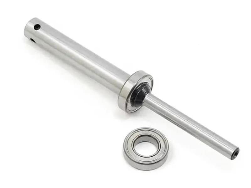
Quick Answer: A tolerance press fit defines the controlled dimensional relationship between a shaft and its mating hole — the allowable variation that determines whether assembly produces interference, transition, or clearance. Interference fits (ISO H7/p6) create radial contact pressure for torque transmission without fasteners; transition fits (H7/k6) balance positional accuracy and assembly ease; clearance fits (H7/g6) allow rotation. Correct fit selection requires calculating interference range, contact pressure, and assembly force — accounting for material elasticity, surface finish, temperature effects, and tolerance stack-up across the full assembly.
What Is a Tolerance Press Fit?
A tolerance press fit is the intentional dimensional relationship engineered between a shaft (external cylindrical feature) and a hole (internal cylindrical feature), where the allowable variation — the tolerance — determines the mechanical behavior of the assembled joint. It is a functional tolerance, not merely a dimensional control: the tolerance class selected directly determines contact pressure, torque transmission capability, assembly force, vibration resistance, and long-term joint durability.
A 20 mm nominal shaft and a 20 mm nominal hole do not “fit” in any meaningful engineering sense without specifying the tolerance on each. Consider a specific example:
- Shaft tolerance: 20.012 – 20.020 mm
- Hole tolerance: 20.000 – 20.008 mm
The shaft is always larger than the hole across the full tolerance range. Assembly requires force, elastic deformation occurs in both components, and radial contact pressure is generated at the mating interface. That contact pressure is the mechanism that transmits torque, resists axial pullout, and maintains concentricity — all without keys, splines, or fasteners.
This is fundamentally different from specifying, say, a ±0.02 mm bilateral tolerance on a non-functional face. The press fit tolerance determines how the joint performs, not just whether the parts are dimensionally conforming. Selecting the wrong fit class — too loose, too tight, or incorrect for the material pairing — is a functional failure, not a cosmetic one.
According to ISO 286 (Limits and Fits), standardized tolerance combinations such as H7/p6, H7/k6, and H7/g6 define globally recognized fit classes that allow engineers to specify, manufacture, and inspect mating components with predictable assembly behavior across different production sites and suppliers.
Types of Press Fit: Engineering Decision Framework
Interference Fit
An interference fit guarantees that the shaft diameter exceeds the hole diameter across the full tolerance range. Assembly requires force or thermal methods; elastic deformation of both parts generates radial contact pressure proportional to the interference magnitude and material stiffness.
Typical interference range (steel–steel, Ø20–50 mm): Approximately 0.01–0.05 mm depending on ISO tolerance class.
How interference creates holding force: The contact pressure at the mating interface generates friction that resists axial and rotational motion. For a steel-on-steel interference fit, contact pressure of 30–80 MPa is typical for H7/p6 at 30 mm diameter — sufficient to transmit substantial torque without any supplementary fastening.
Applications: Bearing outer rings pressed into housings (preventing outer ring rotation under load), gears mounted on drive shafts (torque transmission), rotor-to-shaft assemblies in electric motors, precision bushings, and any application requiring permanent mechanical retention.
Engineering risks: Excessive interference in thin-wall or aluminum housings causes cracking or permanent deformation. In bearing applications, over-interference reduces bearing internal clearance, increasing preload and shortening service life — bearing manufacturers publish maximum housing interference limits for this reason.
Clearance Fit
A clearance fit ensures that the hole is always larger than the shaft across the full tolerance range, creating a guaranteed gap that allows relative motion between components.
Typical clearance range (ISO H7/g6 at Ø30 mm): 0.007 – 0.041 mm.
Applications: Rotating shafts in plain bearings or bushings, sliding components, precision guide pins requiring easy assembly and disassembly.
Limitation: Clearance fits cannot transmit torque without supplementary fastening (keys, splines, adhesive). The gap that enables rotation also allows relative rotation, making clearance fits unsuitable as the sole retention mechanism in driven assemblies.
Transition Fit
A transition fit occupies the zone between clearance and interference. Depending on where within the tolerance range the actual manufactured dimensions fall, the assembly may produce slight clearance or slight interference.
Typical ISO examples: H7/k6, H7/m6.
Engineering behavior: Transition fits provide better positional accuracy than clearance fits — the near-zero gap minimizes radial play and runout — while avoiding the assembly stress of full interference. They are removable with moderate force, unlike interference fits that typically require a press or thermal disassembly method.
Applications: Alignment dowels, precision tooling components, positioning features where accurate location is required but periodic disassembly is necessary.
Quick Selection Reference
| Application | Recommended Fit | ISO Example | Engineering Reason |
|---|---|---|---|
| Bearing housing (outer ring fixed) | Interference | H7/p6 | Prevent ring rotation under vibration |
| Gear on drive shaft | Interference | H7/r6 | Torque transmission without slip |
| Rotating shaft in housing | Clearance | H7/g6 | Friction reduction, lubrication film |
| Sliding mechanism | Clearance | H8/f7 | Enable smooth relative motion |
| Alignment dowel | Transition | H7/k6 | Location accuracy with removability |
| Precision tooling locator | Transition | H7/m6 | Balance precision and serviceability |
Tolerance Press Fit Calculation: Interference, Contact Pressure, and Assembly Force
Basic Interference Calculation
At the most fundamental level:
Interference = Shaft Diameter − Hole Diameter
Because both shaft and hole have tolerance ranges, engineers evaluate maximum and minimum interference:
- Maximum interference = Maximum shaft diameter − Minimum hole diameter
- Minimum interference = Minimum shaft diameter − Maximum hole diameter
For H7/p6 at Ø30 mm (ISO 286 values):
- H7 hole: 30.000 – 30.021 mm
- p6 shaft: 30.022 – 30.035 mm
- Maximum interference: 30.035 − 30.000 = 0.035 mm
- Minimum interference: 30.022 − 30.021 = 0.001 mm
This range defines the functional variability of the press fit in production. Minimum interference must be sufficient for the required torque or axial load capacity. Maximum interference must not overstress the housing or require assembly force beyond the process capability.
Material Elasticity and Contact Pressure
Contact pressure — the radial pressure at the mating interface — determines torque transmission and axial holding capacity. For a solid shaft in a thick-walled hub, the Lamé (thick-walled cylinder) equations give:
Contact pressure is proportional to:
- Interference magnitude
- Material Young’s modulus
- Inversely proportional to diameter and geometry factors
For a steel shaft (E = 210 GPa) pressed into a steel hub with 0.02 mm interference at Ø30 mm, contact pressure is approximately 40–50 MPa. The same interference with an aluminum hub (E = 70 GPa) produces approximately 15–20 MPa — 60–70% less, because aluminum deforms more readily for the same interference magnitude.
This is the quantitative reason why aluminum housings require lower interference than steel housings for the same application. Using an H7/p6 fit specified for a steel housing in an aluminum housing will typically overstress the aluminum (risk of cracking) while simultaneously producing less contact pressure than intended — both the wrong direction.
Surface Roughness Reduces Effective Interference
Surface roughness at the mating interface matters because surface peaks compress during assembly, reducing the effective interference that generates contact pressure. For Ra 1.6 µm surfaces (typical CNC turning finish), effective interference is reduced by approximately 0.002–0.005 mm compared to the nominal dimensional difference.
For tight press fit applications — bearing seats, precision gear hubs — surface roughness should be controlled to Ra 0.8–1.6 µm. Rougher surfaces create unpredictable holding force through uneven peak compression; smoother surfaces (below Ra 0.4 µm) with lubrication present can significantly reduce friction coefficient, which reduces torque capacity even at adequate contact pressure.
Assembly Force Calculation
Press fit assembly force depends on contact pressure, contact area, and friction coefficient:
Assembly Force ≈ Contact Pressure × π × D × L × μ
Where D is diameter, L is engagement length, and μ is friction coefficient.
For a steel shaft, Ø40 mm, 30 mm engagement length, 0.02 mm interference (typical H7/p6), and μ = 0.12 (dry steel):
- Contact pressure ≈ 45 MPa
- Assembly force ≈ 45 × π × 0.040 × 0.030 × 0.12 ≈ 20 kN
At 0.03 mm interference, contact pressure rises to approximately 68 MPa, and assembly force approaches 30 kN. This non-linear increase — a 50% increase in interference producing 50% more force — is why over-interference rapidly escalates from manageable press loads to forces that risk component damage or require special equipment.
In our production experience with press fit components for industrial automation and automotive customers, assembly force calculations performed before machining tolerances are finalized consistently identify interference combinations that would be marginal or damaging — particularly in aluminum housing applications where the calculation is easily overlooked by designers familiar with steel-on-steel assemblies.
Thermal Expansion Effects
Differential thermal expansion between shaft and housing materials is one of the most frequently underestimated factors in press fit design. The coefficients of thermal expansion:
- Steel: 11–13 µm/m·K
- Aluminum: 23 µm/m·K (approximately twice steel)
- Engineering plastics: 60–150 µm/m·K
For a steel shaft in an aluminum housing operating at 80°C above assembly temperature (common in automotive and industrial drive applications), the differential expansion for a Ø50 mm assembly over 80°C:
- Steel expansion: 50 × 0.012 × 80 = 0.048 mm diameter increase
- Aluminum expansion: 50 × 0.023 × 80 = 0.092 mm diameter increase
- Differential: 0.044 mm reduction in effective interference
An initial interference of 0.030 mm — adequate at assembly temperature — becomes a 0.014 mm effective clearance at 80°C operating temperature. The joint has lost all retention capacity.
This calculation is why engineers specify higher nominal interference to compensate for thermal expansion differential, or use thermal assembly methods (heating the housing, cooling the shaft) that allow slightly higher interference while managing assembly stress. The correct approach is to calculate interference at assembly temperature and verify it at maximum and minimum operating temperatures.
ISO 286 Tolerance Standards: Understanding H7/p6, H7/k6, and H7/g6
ISO 286 (Limits and Fits) is the international standard that defines allowable dimensional variation for shafts and holes in a way that creates predictable, interchangeable fit behavior across different manufacturers worldwide. It is the standard foundation of tolerance press fit specification in CNC machining.
The Two Key Parameters
Tolerance grade (IT level) — defines the size of the allowable variation zone. Lower IT numbers mean tighter tolerances: IT5 is tighter than IT7, which is tighter than IT9. The IT number scales with diameter — for a 30 mm nominal diameter, IT7 corresponds to approximately 21 µm; IT6 corresponds to 13 µm.
Fundamental deviation (letter code) — defines the position of the tolerance zone relative to the nominal size. Hole tolerances use uppercase letters (H, G, K, P); shaft tolerances use lowercase (g, k, p).
The H designation for holes specifies that the lower tolerance limit is at the nominal size — H7 at Ø30 mm is 30.000 – 30.021 mm. This makes H the natural reference for hole-basis fit systems, which is the standard approach for most CNC machined assemblies.
Standard Fit Combinations for Press Fit Applications
H7/g6 (Clearance Fit)
- H7 hole: 30.000 – 30.021 mm
- g6 shaft: 29.980 – 29.993 mm
- Result: 0.007 – 0.041 mm clearance always
- Use: Rotating shafts in plain bearings, sliding components
H7/k6 (Transition Fit)
- H7 hole: 30.000 – 30.021 mm
- k6 shaft: 29.002 – 30.015 mm
- Result: -0.015 mm to +0.019 mm (slight interference to slight clearance)
- Use: Alignment dowels, positioning components, moderate retention
H7/p6 (Interference Fit)
- H7 hole: 30.000 – 30.021 mm
- p6 shaft: 30.022 – 30.035 mm
- Result: 0.001 – 0.035 mm interference always
- Use: Bearing seats, gear hubs, permanent drive connections
H7/r6 and H7/s6 (Higher Interference) These combinations provide more interference than H7/p6 and are used when higher torque capacity or more positive retention is required — gear-to-shaft connections under heavy cyclic torque, for example.
Why ISO Standardization Matters for OEM Procurement
Specifying “tight fit” to a machining supplier communicates nothing verifiable. Specifying “H7/p6 per ISO 286” communicates exact dimensional limits for both components, the expected interference range, and the inspection criteria — in a language that any precision machining shop worldwide understands and can verify with standard gauging.
For OEM procurement teams managing multi-supplier production, ISO fit designations prevent the ambiguity that leads to batches of parts that pass individual dimensional inspection but produce inconsistent interference when assembled. The shaft can measure within drawing tolerance and the housing can measure within drawing tolerance, yet the assembled interference falls outside the functional range — if the tolerances were specified independently rather than as a coordinated fit pair.
Key Factors That Affect Press Fit Performance
Material Pairing
The single most important material factor is Young’s modulus — how stiff the material is. Higher modulus materials generate more contact pressure for the same interference, which means more torque capacity but also more assembly stress.
Steel–steel: E = 210 GPa for both. The standard design basis for most ISO press fit tables. Tolerates moderate-to-high interference values.
Steel–aluminum: Aluminum at E = 70 GPa deforms approximately 3× more readily than steel for the same contact pressure. Required interference is lower than steel-on-steel, and thin-wall aluminum housings are particularly vulnerable to cracking under excessive press force. Additionally, aluminum’s 2× higher thermal expansion coefficient means retention force decreases substantially at elevated operating temperatures.
Steel–engineering plastic: Plastics have E values of 2–8 GPa and high thermal expansion (60–150 µm/m·K). Press fits in plastic components must be designed conservatively, accounting for creep deformation under sustained load and significant interference loss at elevated temperature. Many designs substitute adhesive bonding, threaded inserts, or mechanical retention features for interference fit in plastic-to-metal assemblies.
Surface Finish
Control Ra to 0.8–1.6 µm for precision press fit interfaces. Below 0.4 µm, lubrication effects during assembly can reduce friction coefficient enough to require redesign of the interference to maintain torque capacity. Above 2.0 µm, unpredictable peak compression creates variable holding force across production batches.
Load Type and Contact Length
Static loads (fixed bushings, alignment features) can be retained by lower contact pressure than dynamic loads (rotating gear shafts, motor rotors under cyclic torque). Dynamic applications require interference that provides contact pressure well above the minimum for static friction, providing a safety margin against micro-slip under transient overload conditions.
Contact length matters proportionally: doubling engagement length doubles the friction force capacity at the same contact pressure. Where space permits, increasing engagement length is often more efficient than increasing interference (which escalates assembly force and housing stress).
Press Fit in CNC Machining: Capability and Process Control
Achievable Tolerance Levels
| Machining Process | Typical Diameter Tolerance | Suitability for Press Fit |
|---|---|---|
| Standard CNC turning/boring | ±0.02–0.05 mm | Clearance fits, loose transition |
| Precision CNC boring | ±0.01–0.02 mm | Transition fits, lighter interference |
| Fine boring / CBN boring | ±0.005–0.01 mm | Interference fits (H7/p6 class) |
| Reaming | ±0.005–0.015 mm | Transition and interference fits |
| Internal grinding | ±0.002–0.005 mm | Tight interference, bearing seats |
For H7/p6 at Ø30 mm, where the shaft tolerance band is 13 µm wide, achieving consistent production requires process capability (Cpk) that places the distribution well within this band — which typically requires fine boring or grinding, not standard turning.
What Affects Dimensional Stability in Production
Thermal drift during machining — heat from cutting expands the workpiece. A 10°C temperature rise in a 50 mm diameter steel part expands the diameter by approximately 0.006 mm — half the tolerance band for IT6. Long production runs without thermal compensation cause systematic dimensional drift.
Tool wear — worn boring tools shift effective cutting diameter progressively. In tight tolerance work, tool compensation (offset adjustment between passes) is required, and tool life monitoring is essential to prevent out-of-tolerance parts from accumulating before detection.
Thin-wall springback — thin-wall bores expand slightly when unclamped after machining. The released elastic deformation from clamping forces changes the diameter between the machined condition and the measured condition. This is particularly relevant for aluminum housings and must be accounted for in setup.
Bore geometry, not just diameter — a bore that is 30.012 mm on average but 0.008 mm out-of-round creates uneven contact pressure at the press fit interface, with high stress at the major axis and low (or zero) contact at the minor axis. Roundness should be specified separately from diameter tolerance, typically at ≤50% of the diameter tolerance value. For H7/p6, specifying roundness ≤ 0.005 mm is appropriate.
Inspection Methods for Press Fit Components
Standard dimensional inspection (micrometers, bore gauges) confirms diameter within tolerance, but press fit performance depends on more than diameter. Complete inspection of precision press fit components should include:
- Bore/shaft diameter — confirmed to the specified IT tolerance class
- Roundness and cylindricity — CMM or roundness tester; ensures even contact pressure distribution
- Surface roughness — Ra measurement to confirm 0.8–1.6 µm as-machined
- Concentricity — CMM measurement to verify bore axis alignment with reference datum
For high-volume production, air gauging systems measure bore diameter with resolution of ±0.001 mm and cycle time of under 5 seconds per part — far faster than CMM inspection while providing the accuracy required for IT6–IT7 tolerance verification.
Common Press Fit Problems, Root Causes, and Solutions
Problem 1: Housing Cracking or Excessive Assembly Force
Symptoms: Housing cracks during pressing, bearing preload increases unexpectedly, shaft scoring, hydraulic press overload.
Root causes: Excessive interference for the housing material or wall thickness; assembly at room temperature when thermal methods should be used; aluminum housing with steel-housing interference specification.
Solutions:
- Recalculate required interference based on actual torque/load requirement — many designs use excessive interference inherited from steel-housing standards without adjustment for aluminum
- Increase housing wall thickness in design if interference cannot be reduced
- Use thermal assembly (heat housing to 80–120°C) to reduce required press force by 40–70%
- Switch to H7/n6 or H7/m6 if H7/p6 is overstressing the specific geometry
Problem 2: Bearing Outer Ring Rotation (Creep)
Symptoms: Bearing outer ring rotates in housing, overheating, noise, rapid bearing wear.
Root causes: Insufficient interference; Ra surface too smooth with lubricant present (low friction coefficient); thermal expansion reducing effective interference at operating temperature.
Solutions:
- Increase interference class (from H7/m6 to H7/p6 for example)
- Verify surface finish is Ra 0.8–1.6 µm — not smoother
- Recalculate interference at operating temperature, not assembly temperature
- Check housing bore geometry (out-of-round reduces average contact pressure)
Problem 3: Fretting Corrosion Under Dynamic Load
Symptoms: Rust-colored debris at the interface, micro-pitting on mating surfaces, progressive loss of concentricity, noise.
Root causes: Insufficient contact pressure allowing micro-slip under cyclic loading; excessive clearance from under-interference or thermal expansion; low engagement length relative to applied torque.
Solutions:
- Increase interference to eliminate micro-movement under maximum load
- Extend engagement length to increase friction capacity
- Verify that maximum transmitted torque with safety factor does not exceed the joint’s friction capacity at minimum interference and maximum operating temperature
Problem 4: Thermal Loosening at Operating Temperature
Symptoms: Retention force drops at elevated temperature, joint allows movement or pull-out force falls below requirement, static assembly check passes but dynamic test fails.
Root causes: Insufficient nominal interference to compensate for differential thermal expansion; steel shaft in aluminum housing without thermal compensation calculation.
Solutions:
- Calculate interference at operating temperature using differential CTE, not only at room temperature assembly temperature
- Increase nominal interference to maintain minimum required interference at maximum operating temperature
- Consider thermal assembly method to allow higher nominal interference without excessive room-temperature assembly force
Tolerance Stack-Up in Press Fit Assemblies
Individual component tolerances are only part of the press fit design challenge. Multi-component assemblies accumulate dimensional variation, and worst-case stack-up can push an assembly outside the functional interference range even when every individual part passes inspection.
How Stack-Up Affects Press Fit Performance
In a typical bearing assembly — shaft, bearing inner ring, bearing outer ring, housing bore — each component contributes its own dimensional variation. If shaft is at maximum material condition and housing bore is at minimum material condition, the resulting interference is at maximum. If both are at minimum and maximum respectively, interference is at minimum. The functional requirement is that minimum interference still exceeds the threshold for the required torque or retention, and maximum interference does not overstress the housing.
Worst-case analysis calculates both extremes and verifies the assembly functions at both. Statistical analysis (root-sum-square method) calculates the probability of extreme stack-up conditions — more realistic for production where all dimensions are statistically distributed around their nominal values, but requires process capability data.
Geometric Tolerance Interaction
Cylindricity and roundness variation contribute to stack-up in ways that dimensional tolerances alone do not capture. A bore with 0.010 mm cylindricity error (within its diameter tolerance band) creates 0.010 mm variation in effective contact pressure around the circumference. At the major axis of an oval bore, interference and contact pressure are higher than nominal; at the minor axis, they may be below the functional minimum. This variation is why geometric tolerances must be specified alongside dimensional tolerances for precision press fit components.
DFM Guidelines for Tolerance Press Fit Design
Avoid Over-Specification of Interference
The most common press fit DFM error in our production experience reviewing customer drawings is interference over-specification — using H7/p6 where H7/m6 would adequately meet the load requirement, or inheriting steel-housing interference specifications for aluminum housings. Over-tight interference increases machining cost (tighter tolerance requires more process steps), assembly difficulty, rejection rate, and risk of component damage, all without functional benefit if the design torque and retention can be achieved at lower interference.
Before finalizing fit class, calculate the required contact pressure from the torque or retention load requirement, add a safety factor of 1.5–2.0, and work backward to the minimum required interference. Then confirm that the maximum interference at the chosen tolerance class does not overstress the housing.
Specify Geometric Tolerances Alongside Dimensional Tolerances
A drawing that specifies H7/p6 on a bearing housing bore is incomplete without roundness (≤ 0.005 mm recommended for IT7-class press fits) and cylindricity (≤ 0.008 mm over 50 mm bore length). Without these controls, a bore that measures within diameter tolerance but has significant roundness error will create uneven contact pressure that reduces holding capacity below the calculated value.
Account for Temperature in Material Pairing
All steel-on-aluminum press fits require thermal analysis. Calculate effective interference at assembly temperature and at maximum operating temperature. If minimum effective interference at operating temperature falls below the required minimum, increase nominal interference or switch to thermal assembly method.
Design for Assembly Method Feasibility
Assembly force must be achievable with the equipment available in production. A 50 kN press force calculation for a ±100-piece daily production volume requires a hydraulic press of appropriate capacity, correct tooling for alignment, and a controlled process to prevent misalignment cracking during insertion. For interference fits requiring more than approximately 30–50 kN, thermal assembly (heating the housing or cooling the shaft) is typically more practical, reduces misalignment risk, and allows slightly higher interference.
DFM Checklist for Press Fit Components
| Design Question | DFM Action |
|---|---|
| Is the interference requirement calculated from actual load, not default standard? | Perform torque/retention calculation before selecting fit class |
| Is material pairing accounted for in interference selection? | Reduce interference for aluminum vs steel standard |
| Are thermal expansion effects calculated at operating temperature? | Verify minimum interference at Tmax, not only at assembly temperature |
| Are geometric tolerances (roundness, cylindricity) specified? | Add roundness ≤ 50% of diameter tolerance band |
| Is assembly force within process capability? | Calculate press force at maximum interference; evaluate thermal assembly if >30 kN |
| Is surface roughness specified at Ra 0.8–1.6 µm? | Include Ra callout on press fit surfaces |
| Has tolerance stack-up been evaluated for the complete assembly? | Run worst-case or RSS analysis on all mating components |
Real Applications: Industry Case Studies
Automotive: EV Motor Rotor Assembly
An electric vehicle motor used a steel shaft pressed into a laminated rotor core with initial specification at H7/p6 (30 mm diameter). During production validation, assembly force exceeded press capacity on approximately 20% of parts, and post-assembly concentricity measurements showed rotor distortion in roughly 12% of assembled units.
Root cause analysis identified that the laminated rotor core’s effective elastic modulus was lower than solid steel (laminations with insulating layers between them), requiring lower interference than a solid steel hub. Additionally, the initial specification had no thermal analysis — motor operating temperature of 120°C with steel shaft in laminated (partially ferrous/adhesive composite) rotor reduced effective interference by more than 50%.
Engineering corrections: Reduced to H7/m6 (nominal interference 0.008–0.025 mm versus original 0.015–0.035 mm), introduced thermal assembly (60°C pre-heat), controlled surface finish to Ra 1.2 µm, added post-assembly CMM concentricity verification.
Results: Assembly force reduced within press capacity, rotor distortion rate below 0.5%, concentricity within specification at both ambient and operating temperature.
Aerospace: Titanium Shaft in Aluminum Control Linkage
A control linkage system used a Ti-6Al-4V shaft pressed into an aluminum 6061 bracket at H7/p6. During thermal endurance testing at simulated operating temperatures of 80°C, the joint showed micro-movement under applied load — the interference that was adequate at assembly temperature had fallen below the functional minimum under thermal differential expansion.
Engineering solution: Recalculated interference requirement at 80°C operating temperature. Differential expansion for the 12 mm diameter joint over 80°C produced 0.018 mm reduction in effective interference (titanium CTE 8.6 µm/m·K versus aluminum 23 µm/m·K, over 12 mm diameter, 80°C delta = 0.018 mm). Nominal interference increased to maintain minimum 0.010 mm effective interference at 80°C. Verified through thermal cycling tests to confirm no movement under specified load at operating temperature.
Medical: Precision Instrument Hub
A surgical instrument hub used a stainless steel shaft in a precision stainless steel housing at H7/p6. Post-assembly CMM inspection showed concentricity variation of 0.012 mm — exceeding the instrument’s 0.005 mm concentricity requirement.
Root cause: The housing bore had passed diameter inspection (within H7 tolerance) but had 0.009 mm roundness error. The out-of-round bore created uneven contact pressure that displaced the shaft axis from the bore axis. The drawing specified only diameter tolerance, no geometric controls.
Engineering correction: Added roundness ≤ 0.004 mm and cylindricity ≤ 0.006 mm to the housing bore specification. Switched from H7/p6 to H7/n6 (transition fit) after fatigue analysis showed the application did not require full interference — positional accuracy was the primary requirement, not high torque retention. CMM verification added to production inspection.
Results: Concentricity within 0.003 mm, rejection rate reduced from 18% to under 2%, torque specification confirmed met at H7/n6 interference level.
Key Takeaways
- A tolerance press fit is a functional specification, not a dimensional check — it directly determines contact pressure, torque capacity, vibration resistance, and assembly behavior.
- ISO 286 provides the standard framework: H7/g6 for clearance (rotation), H7/k6 for transition (positioning), H7/p6 and above for interference (torque transmission and permanent retention).
- Interference range must be calculated — maximum interference must not overstress the housing; minimum interference must provide required contact pressure for the load and safety factor.
- Material pairing changes everything — aluminum housings require approximately 40–60% lower interference than steel housings for the same contact pressure; always calculate, never inherit steel-standard tolerances for aluminum designs.
- Thermal expansion must be analyzed for any steel-in-aluminum or dissimilar-material press fit — differential CTE causes interference to decrease significantly at operating temperature and can eliminate retention entirely.
- Surface finish (Ra 0.8–1.6 µm) and geometric tolerances (roundness, cylindricity) are as critical as diameter tolerance for predictable press fit performance — specify them explicitly.
- For OEM procurement teams, tolerance stack-up analysis across the full assembly is the safeguard against parts that individually pass inspection but produce inconsistent interference in production.
Frequently Asked Questions
What is a tolerance press fit and how does it work?
A tolerance press fit is the controlled dimensional relationship between a shaft and a mating hole, where the allowable variation (tolerance) determines whether assembly produces interference, transition, or clearance. In an interference fit, the shaft is intentionally larger than the hole — assembly requires force, elastic deformation occurs in both parts, and radial contact pressure is generated at the interface. That contact pressure creates the friction that transmits torque, resists axial pullout, and maintains concentricity without fasteners. ISO 286 standardizes these relationships through combinations like H7/p6 (interference), H7/k6 (transition), and H7/g6 (clearance), allowing predictable fit behavior across different manufacturers.
How is press fit interference calculated?
Interference is calculated as shaft diameter minus hole diameter across the tolerance range. Maximum interference equals maximum shaft diameter minus minimum hole diameter; minimum interference equals minimum shaft diameter minus maximum hole diameter. Real-world calculation must also account for material Young’s modulus (which determines contact pressure for a given interference), surface roughness (which reduces effective interference by 0.002–0.005 mm through peak compression), thermal expansion differential (which changes effective interference at operating temperature), and wall thickness of the housing (which affects whether the housing can withstand the assembly stress). Assembly force is calculated from contact pressure, contact area, and friction coefficient — typically running 10–50 kN for industrial shaft diameters at H7/p6 interference.
What is the difference between H7/p6, H7/k6, and H7/g6?
These ISO 286 combinations define different fit classes at the same H7 hole tolerance. H7/g6 is a clearance fit — the g6 shaft is always smaller than the H7 hole, guaranteeing a gap of 0.007–0.041 mm (at Ø30 mm) that allows rotation. H7/k6 is a transition fit — the k6 shaft may be slightly smaller or slightly larger than the H7 hole depending on actual manufactured dimensions, producing either slight clearance or slight interference for accurate positioning. H7/p6 is an interference fit — the p6 shaft is always larger than the H7 hole, guaranteeing interference of 0.001–0.035 mm (at Ø30 mm) that generates contact pressure for torque transmission. The correct combination is determined by the functional requirement — rotation, positioning, or permanent retention.
Why does material pairing affect press fit tolerance selection?
Material pairing determines how much contact pressure is generated per unit of interference (governed by Young’s modulus) and how interference changes with temperature (governed by thermal expansion coefficient). An aluminum housing has roughly one-third the Young’s modulus of steel — the same interference generates 60–70% less contact pressure in aluminum than in steel. This means less interference is needed to generate the required contact pressure, and excessive interference is more likely to crack or permanently deform aluminum. Additionally, aluminum expands roughly twice as fast as steel with temperature, so steel-shaft-in-aluminum-housing assemblies lose effective interference at elevated operating temperatures — a differential of 0.018 mm per 80°C for a 12 mm diameter joint. Both effects must be calculated, not assumed away.
When should thermal assembly (shrink fitting) be used instead of cold pressing?
Thermal assembly should be considered when: calculated assembly force exceeds approximately 30–50 kN and risks component misalignment during pressing; the interference required for the load capacity would cause excessive assembly stress in cold-press conditions; the housing material is aluminum or a thin-wall geometry that is sensitive to press force; or precision concentricity after assembly is critical (thermal assembly distributes contact more uniformly than cold pressing, which can cause slight angular misalignment). In thermal assembly, the housing is heated (typically 80–150°C) to expand the bore, allowing the shaft to be inserted with minimal force, then the joint develops full interference as the housing cools. Higher nominal interference is achievable with thermal methods than with cold press for the same assembly stress level.
How does surface roughness affect press fit holding force?
Surface roughness affects press fit in two ways. During assembly, surface peaks compress and flatten, reducing the effective interference that generates contact pressure — typically by 0.002–0.005 mm for Ra 1.6 µm surfaces. After assembly, the friction coefficient at the contact interface determines how contact pressure converts to torque and axial load capacity. Optimal Ra for precision press fits is 0.8–1.6 µm: rough enough for adequate friction coefficient (μ ≈ 0.10–0.15 dry), smooth enough for predictable interference through controlled peak compression. Surfaces rougher than Ra 2.5 µm produce unpredictable and variable holding force; surfaces below Ra 0.4 µm with lubrication present can reduce friction coefficient below 0.08, requiring increased interference to compensate.
What role does tolerance stack-up play in press fit assemblies?
Tolerance stack-up determines the range of actual interference achieved in production assemblies, as opposed to the nominal interference calculated from part drawings. In a multi-component assembly, each part’s dimensional variation accumulates: if the shaft is at maximum material condition and the housing is at minimum material condition simultaneously, interference is at maximum. If both are at opposite extremes, interference is at minimum. Worst-case analysis verifies that minimum interference still provides required load capacity with safety factor, and maximum interference does not overstress the housing. Geometric tolerances (roundness, cylindricity) contribute additional effective variation — an out-of-round bore within its diameter tolerance creates uneven contact pressure that reduces average holding capacity below the calculated value. Specifying roundness ≤ 50% of the diameter tolerance band limits this geometric contribution to stack-up.
Written by the CMS engineering team with 15+ years of precision CNC machining experience in tolerance press fit components, bearing seats, gear assemblies, and precision rotating machinery for automotive, aerospace, medical, and industrial OEM applications. Technical references: ISO 286-1 (Limits and Fits System), ISO 286-2 (Tables of Standard Tolerance Grades), ASME B4.1 (Preferred Limits and Fits), Shigley’s Mechanical Engineering Design (Interference Fit Design Chapter).
Sourcing Precision Press Fit Components With Verified Interference Ranges?
At CMS, we manufacture bearing seats, gear hubs, precision shafts, and custom press fit assemblies with full interference range verification — confirming both diameter and geometric tolerances (roundness, cylindricity) at production quantities. Every press fit component job includes DFM review of interference calculation, material pairing analysis, and assembly force feasibility before machining begins. We provide inspection reports that document not just diameter conformance but the complete geometric condition needed to predict assembly behavior.
[Request a DFM review and tolerance press fit quote →]


