
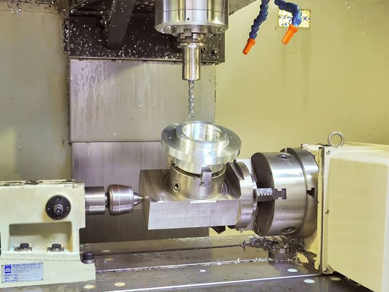
4-axis CNC machining is a process where the cutting tool or the workpiece can rotate around an additional axis—usually the A-axis—while still moving along X, Y, and Z. This extra rotation makes it possible to machine multiple sides of a part in a single setup, improving accuracy and reducing machining time.
In modern manufacturing, this capability matters because many parts now include features around their perimeter or on several faces.
Compared with 3-axis machining, 4-axis equipment handles these geometries more efficiently. Compared with 5-axis machining, it provides many of the same advantages but with lower cost and simpler programming, making it a practical middle option for many engineering teams.
This guide is written for engineers, designers, and procurement managers who want a clear and practical understanding of 4-axis CNC machining. We will explain how it works, where it fits between 3-axis and 5-axis systems, the tolerances you can expect, and the types of parts that benefit most from this process.
Fundamentals of 4-Axis CNC Machining
What Is a 4-Axis CNC Machine?
-
VMC: Rotary table on the bed, ideal for smaller parts and simpler setups.
-
HMC: Rotary table mounted vertically, improving chip evacuation for heavier parts or longer jobs.
-
Side machining without re-clamping
-
Radial or spiral milling on cylindrical surfaces
-
Multi-face machining in one setup, reducing tolerance errors
Indexing vs. Simultaneous 4-Axis (3+1 vs. Continuous 4-Axis)
3+1 Axis (Indexing 4-Axis)
-
Machining holes on multiple sides
-
Pocket or slot features around the perimeter
-
Manual or automated part reorientation replaced by programmed indexing
Continuous 4-Axis (Simultaneous)
-
Helical or spiral machining
-
Turbine-like contours
-
Cylindrical engraving
-
Camshaft or complex curvature milling
Key Machine Components of a CNC 4-Axis Milling Machine
-
Spindle: Provides cutting power and maintains rigidity during multi-sided machining.
-
Rotary Table (A-axis): The core of 4-axis capability; its accuracy directly affects angular positioning and multi-face tolerances.
-
Servo Motors & Drives: Control both linear and rotational movements with high precision.
-
CNC Controller (Fanuc, Siemens, Heidenhain): Interprets G-code, manages 3+1 or simultaneous motion, and compensates for rotary-axis kinematics.
-
Tool Magazine (ATC): Enables automatic tool changes for machining from multiple angles without interruption.
-
Work Coordinate System (G54, G55, etc.): Defines fixed reference points for multi-side machining.
-
Rotary Centerline Calibration: Ensures the toolpath aligns correctly with the rotational axis to avoid tolerance errors during indexing or continuous machining.
Workholding, Fixturing, and Coordinate Systems in 4-Axis Machining
Workholding Strategies for 4-Axis CNC Machines
• Three-jaw and four-jaw chucks
-
Self-centering chucks provide fast clamping.
-
Four-jaw independent chucks allow fine-tuning for non-concentric stock or irregular shapes.
• Rotary-table fixtures
• V-blocks and collet fixtures
-
V-blocks help prevent rotation and maintain axial alignment.
-
Collets provide uniform clamping pressure and superior concentricity.
• Soft jaws
Choosing fixtures for thin-wall or long-axis components
-
Thin-walled parts require distributed clamping to avoid deformation; soft jaws or custom cradles are preferred.
-
Long parts need axial support (tailstock, steady rest) to prevent bending during rotation.
-
For parts that must maintain tight runout—e.g., ±0.01 mm or even ±0.005 mm—fixture repeatability and rigidity are critical. Poor fixturing is often the root cause of stacking tolerance errors in 4-axis machining.
Zero-Point Systems, Alignment, and Center-of-Rotation Setup
• Work offsets (G54–G59)
-
Set G54 at the center of rotation or at a key datum.
-
Use G55, G56… for alternate fixture locations or reorientation.
-
Define the A-axis zero such that the part’s primary face is perpendicular to the spindle.
• Common sources of positioning error
-
Rotary center misalignment: even a 0.02 mm shift will distort angular features.
-
Eccentricity of the part to the A-axis centerline: leads to varying wall thickness or inconsistent diameters.
-
Coaxiality errors: when fixtures or soft jaws are not machined in situ.
-
Tilt or angular deviation in the trunnion or rotary table.
• Methods for calibration and verification
-
Test bars to check axial alignment and runout
-
Dial indicators to sweep the rotary table or verify trunnion tilt
-
Laser tool setters or touch probes to define precise offsets
-
Indicator loops to check repeatability after clamp/unclamp cycles
Minimizing Error Accumulation During Multi-Face Machining
• Тепловая деформация
-
Allow the machine to reach thermal stability before final finishing.
-
Use consistent coolant flow and avoid sudden temperature changes.
• Clamping force and deformation
-
Use soft jaws, wider clamping surfaces, or step jaws.
-
Consider vacuum fixtures for extremely delicate components.
• Residual stresses
-
Stress-relief heat treatment or rough-cut + natural aging helps stabilize geometry.
-
Symmetrical machining around the part’s axis reduces distortion.
• Reducing indexing shift (angular misalignment)
-
Use fixtures with high repeatability (±0.005 mm if possible).
-
Avoid heavy, unbalanced parts that load the A-axis unevenly.
-
Apply probing routines to re-verify datum after indexing.
• Controlling coaxiality, runout, and parallelism
-
Machine jaws or fixtures in place to minimize runout.
-
Perform finish passes after the final index movement.
-
Use probing to compensate for slight position errors.
Toolpaths and Process Parameters for 4-Axis CNC Machining
4.1 CAM Strategies for 4-Axis CNC Milling Machine
● Rotary Machining
-
Cylindrical or tubular parts
-
Helical grooves
-
Decorative or functional patterns wrapped around a shaft
● Swarf Cutting
-
Angled walls
-
Фаски
-
Thin-wall components
● Morph Spiral / Morph Between Curves
-
Turbine blade fillets
-
Aerofoil transitions
-
Continuous decorative surfaces
● Wrapped Toolpaths
-
Logos
-
Text engraving
-
Small detailed features on round parts
● Typical 4-Axis Machining Examples
-
Helical side machining for fluid components or decorative spirals
-
Cylindrical profiling for shafts and rollers
-
Indexing and continuous machining for impellers or multi-facet components
Cutting Parameters and Tool Selection
● Aluminum Alloys (6061 / 7075)
-
Spindle speed: 12,000–24,000 rpm
-
Feed per tooth: 0.03–0.08 mm/tooth
-
Radial DOC: 0.2–0.5 ×D Notes: Aluminum evacuates chips easily during rotation. Keep tools sharp to avoid chatter.
● Stainless Steel (304 / 316 / 17-4PH)
-
Spindle speed: 2,500–6,000 rpm
-
Feed per tooth: 0.01–0.03 mm/tooth
-
Radial DOC: 0.1–0.2 ×D Notes: Stainless steel tends to form built-up edges. Use consistent coolant flow to stabilize temperature.
● Titanium Alloy (Ti-6Al-4V)
-
Spindle speed: 1,500–4,000 rpm
-
Feed per tooth: 0.02–0.05 mm/tooth
-
Radial DOC: 0.05–0.15 ×D Notes: Titanium has poor thermal conductivity. Air blast or through-spindle coolant is highly recommended.
● Engineering Plastics (PEEK, PC, Nylon)
-
Spindle speed: 8,000–18,000 rpm
-
Feed per tooth: 0.04–0.10 mm/tooth Notes: Plastics can melt during continuous rotary cutting. Use high-sharpness tools and control heat.
Special Considerations for Continuous 4-Axis Cutting
-
Keep tool overhang as short as possible
-
Prefer climbing milling to reduce wall chatter
-
Use fewer-flute tools for better chip evacuation
-
For titanium or stainless steel, avoid long periods of uninterrupted cutting to control thermal drift
Surface Finish Considerations and Chip Evacuation
● Controlling Scallop Height
-
Keep scallop height below 0,02–0,05 мм
-
Maintain stable A-axis rotation speed
-
Reduce tool deflection by using a stiffer tool holder
● Chip Evacuation and Cooling
-
Through-spindle coolant → best for steel and deep grooves
-
Air blast → excellent for aluminum and plastics; prevents thermal buildup
-
Flood coolant → common but less effective when the workpiece is spinning rapidly
● Common 4-Axis Machining Defects and Solutions
-
Side-wall chatter
-
Taper caused by heat buildup
-
Concentricity deviation (runout)
Achievable Tolerances, Surface Integrity, and Quality Control
Typical Tolerances Achievable with a 4-Axis CNC Vertical Machining Center
● Single-Setup (Continuous or Simultaneous 4-Axis)
-
Typical geometric tolerance: ±0,005–0,02 мм
-
Achievable on well-fixtured, medium-length shafts, thin-wall cylindrical parts, and rotational features.
-
Advantage: Only one setup, no indexing errors, consistent A-axis alignment.
● Multi-Indexing (3+1 Axis)
-
Typical geometric tolerance: ±0,01-0,03 мм
-
Slightly lower precision due to repeatability of the rotary table and fixturing.
-
Ideal for complex multi-face parts or features inaccessible in a single orientation.
● Comparison with 3-Axis and 5-Axis
-
3-осевой: Limited for side-wall machining; multi-setup required for complex geometry; tolerances similar to multi-indexing 4-axis.
-
5-axis: Achieves ±0.002–0.01 mm on similar features due to simultaneous tilting; better for undercuts and complex curves.
-
4-осевой: Sits in between 3-axis and 5-axis in capability and cost-efficiency; ideal for cylindrical and multi-face prismatic parts without the complexity of full 5-axis kinematics.
Influence of Rotation, Clamping, and Tool Deflection on Accuracy
● Tool Overhang and Deflection
-
Long or slender cutters on deep or thin features are prone to bending, affecting surface finish and dimensional accuracy.
-
Compensation strategies include reducing tool overhang, using larger diameter or stiffer tools, and adjusting feed rates.
● Rotary Axis Effects
-
High A-axis speeds can induce vibrations, especially in thin-wall or long parts.
-
Proper spindle speed/feed ratio ensures stability and minimizes chatter or taper.
● Clamping and Fixturing
-
Over-tightening may deform thin walls or shafts; under-tightening causes movement under cutting forces.
-
Soft jaws, V-blocks, and tailstock supports help maintain coaxiality and reduce runout.
● Feed and Cutting Compensation
-
CNC systems can compensate for tool deflection by adjusting the programmed path.
-
Some CAM systems allow real-time adaptive feed strategies to maintain constant chip load while reducing deflection-induced errors.
Inspection and Verification for 4-Axis Machined Parts
● CMM and Datum Alignment
-
Coordinate Measuring Machines (CMM) are commonly used to verify multi-face features.
-
Key steps:
-
Establish primary datum in the rotational center.
-
Align secondary features using G54/G55 work offsets.
-
Perform multi-feature inspection in one setup to minimize error accumulation.
-
● Key Features to Inspect
-
Concentricity: Between cylindrical surfaces and A-axis rotation center
-
Perpendicularity and verticality: Especially on thin walls or flanges
-
Биение: Radial deviation of shafts or rotational features
-
Hole location and side-wall profile: Critical for assembly and mechanical fit
● Residual Stress and Surface Integrity
-
Residual stress from clamping or material removal can distort thin-walled parts after release.
-
Surface integrity checks (roughness, micro-cracks) are important for fatigue-sensitive applications such as aerospace or medical components.
-
Non-destructive testing (NDT), such as dye penetrant or X-ray inspection, may be required for critical parts.
Applications and Industry Use Cases of 4-Axis CNC Machining
Typical Part Types Suitable for 4-Axis CNC Machining
-
Cylindrical parts: Shafts, rollers, pins with grooves, slots, or flutes.
-
Housings and enclosures: Small-to-medium-sized shells with side openings or ribs.
-
Tubular components: Pipes, hydraulic fittings, and hollow shafts with machined ends or side features.
-
Tapered components: Conical shafts or fixtures requiring spiral milling or angled grooves.
-
Adjacent multi-face features: Parts that would otherwise require multiple setups on a 3-axis machine, including side holes, slots, or fillets.
Applications Across Key Industries
● Aerospace
-
Engine brackets, fuselage supports, housings, and lightweight aluminum or titanium assemblies
-
4-axis machining allows side features and rotational profiles to be machined in a single setup, improving concentricity and reducing rework.
● Automotive
-
Transmission shafts, aluminum housings, mounting brackets, and custom jigs/fixtures
-
Side holes, grooves, and ribs can be machined efficiently without multiple indexings.
● Medical
-
Surgical instruments, titanium implants, orthopedic components
-
Maintaining tight tolerances and surface finish is critical; 4-axis machining reduces handling and improves reproducibility.
● Robotics and Industrial Automation
-
Precision joint components, actuator shafts, splines, and end-effectors
-
High concentricity and surface integrity are essential for motion accuracy and longevity.
Case Study: 3-Axis vs. 4-Axis — Time and Cost Comparison
| Параметр | 3-осевая обработка | 4-осевая обработка |
| Setups required | 3 | 1 |
| Total machining time | 8 hours | 5 hours |
| Geometric accuracy | ±0,02 мм | ±0,01 мм |
| Scrap / rework risk | Средний | Низкий |
| Labor involvement | High (manual re-fixturing) | Низкий |
Key Observations
-
3-axis machining requires multiple setups, increasing cumulative positioning errors and the likelihood of scrap.
-
4-axis machining reduces setup time and improves feature alignment, especially for cylindrical or multi-side features.
-
The return on investment (ROI) for a 4-axis machine becomes significant when producing medium-volume or precision-critical parts. Even modest production runs benefit from fewer setups, lower scrap, and higher consistency.
When to Выбрать 3-, 4-, or 5-Axis CNC Machining
Comparing 3-, 4-, and 5-Axis Capabilities
| Тип оси | Сильные стороны | Ограничения | Типичные области применения |
| 3-осевая | Simple programming, lower cost, fast for prismatic parts | Limited to top-down machining; multiple setups needed for side features | Simple housings, plates, slots, pockets |
| 4-осевая | Adds a rotational axis (A-axis); enables side-wall and multi-face machining in one setup; cost-effective | Cannot handle full tilt or undercuts like 5-axis; CAM slightly more complex than 3-axis | Shafts, cylindrical housings, multi-face components, tapered or helical features |
| 5-осевая | Simultaneous tilting and rotation; best for complex surfaces, undercuts, and aerodynamic profiles | Higher machine cost, more complex programming, longer setup | Impellers, turbine blades, aerospace components with freeform surfaces |
The “Sweet Spot” for 4-Axis Machining
-
One setup suffices for most features
-
Reduces repositioning errors compared with 3-axis indexing
-
Improves concentricity for shafts, cylinders, and multi-face parts
-
-
Moderate complexity parts
-
Side holes, helical grooves, or shallow angled surfaces
-
Not requiring simultaneous tilting for deep undercuts
-
-
Cost-sensitive projects
-
Less expensive than full 5-axis machines
-
Lower programming and fixture complexity
-
Shorter learning curve for CAM programmers
-
-
Balanced production volume
-
High enough to justify investment over repeated 3-axis setups
-
Low enough that 5-axis may be overkill
-
Design for Manufacturability (DFM) Recommendations
-
Align features along the rotational axis wherever possible
-
Minimize deep, thin-wall features that may deflect under cutting forces
-
Design multi-face features to be reachable in a single setup
-
Avoid complex undercuts or extreme tilt angles, which would require 5-axis
-
Consider tool accessibility and length-to-diameter ratio to prevent deflection and chatter
Резюме
Часто задаваемые вопросы
What is the difference between 3-, 4-, and 5-axis CNC machining?
-
3-axis: Moves along X, Y, Z axes. Suitable for prismatic or simple multi-face parts, but often requires multiple setups.
-
4-axis: Adds a rotational A-axis (around X-axis), enabling side-wall, cylindrical, and multi-face machining in fewer setups. Best for shafts, housings, and tapered or helical features.
-
5-axis: Adds simultaneous tilting and rotation. Ideal for complex surfaces, deep undercuts, and aerodynamic profiles but requires higher investment and programming complexity.
-
Choose 4-axis when parts are rotationally symmetric or have multiple side features accessible by a single rotational setup.
-
It offers a “sweet spot”: better capability than 3-axis, lower cost and complexity than 5-axis.
-
Best suited for medium-complexity components in aerospace, automotive, medical, and industrial automation applications.
-
Cylindrical components: shafts, rollers, pins
-
Multi-face housings and enclosures with side holes or ribs
-
Tubular or conical parts with angled grooves or helical features
-
Multi-feature prismatic parts requiring indexing or continuous rotation
-
Single-setup (continuous 4-axis): ±0.005–0.02 mm
-
Multi-indexing (3+1): ±0.01–0.03 mm
-
Accuracy depends on fixturing, rotary axis calibration, tool deflection, and thermal or residual stresses. Proper setup and inspection are critical.
-
Stable and precise clamping minimizes runout, indexing errors, and deflection.
-
Common fixtures: 3-jaw chucks, rotary tables, V-blocks, soft jaws.
-
Thin-wall parts or long shafts require support to prevent vibration or bending.
-
Rotary machining – for cylindrical or conical features
-
Swarf cutting – for side-wall material removal
-
Morph spiral / morph between curves – smooth transition along surfaces
-
Wrapped toolpaths – for features mapped onto a cylinder or tube
-
Strategy choice affects cycle time, surface finish, and tool life.
-
Aluminum alloys: High speed, moderate feed; low cutting forces
-
Stainless steels (304, 316, 17-4PH): Slower feed, higher DOC; heat generation and tool wear must be managed
-
Titanium (Ti-6Al-4V): Low thermal conductivity; avoid overheating and maintain rigidity
-
Engineering plastics (PEEK, PC, Nylon): High spindle speed; controlled chip evacuation to prevent melting
-
CMM measurement: Primary datum alignment, concentricity, perpendicularity, runout, hole positions
-
Surface integrity checks: Roughness, micro-cracks, residual stress evaluation
-
Non-destructive testing (NDT) may be required for aerospace, medical, or fatigue-critical components.
-
Yes, by reducing setups, scrap, and manual repositioning.
-
Example: An aluminum housing with side holes can require 3 setups on a 3-axis machine, but only 1 setup on a 4-axis machine, saving time, reducing errors, and improving ROI.
-
Align features along the rotational axis whenever possible
-
Minimize thin walls or long overhangs prone to deflection
-
Design multi-face features to be reachable in a single setup
-
Ensure tool accessibility and appropriate tool length-to-diameter ratio


