
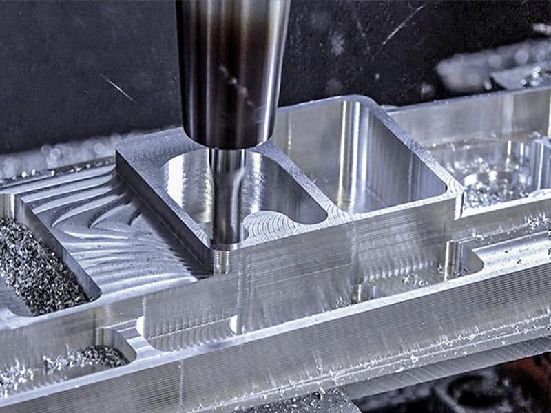
End milling is a core CNC machining operation that enables precise three-dimensional geometry creation and forms the backbone of modern milling processes. Its value lies in controlled material removal that translates digital designs into accurate, repeatable features.
Because end milling cuts in multiple directions, it is essential for producing pockets, slots, contours, and complex cavities. Understanding how end milling works helps engineers design manufacturable parts, enables stable and efficient machining, and supports informed decisions on cost, tolerance, and supplier capability.
What Is End Milling and How Does It Differ from Other Milling Operations?
End milling is a CNC milling operation in which a rotating cutting tool removes material using both its end (axial direction) and its sides (radial direction). From an engineering perspective, this dual cutting capability is what makes end milling uniquely flexible. An end mill can plunge into material, cut laterally, follow complex contours, and generate three-dimensional features within a single setup.
The defining characteristic of end milling is that axial and radial cutting occur simultaneously. The tool engages the workpiece with its bottom cutting edges to control depth while its peripheral flutes shape walls, profiles, and cavities. This allows end milling to create pockets, slots, contours, and internal features that cannot be produced by operations limited to one cutting direction.
Axial and Radial Cutting in End Milling
In axial cutting, the end mill moves downward into the material, similar to drilling but with a different cutting geometry. In radial cutting, the tool removes material from the side as it moves laterally. The interaction between these two modes determines cutting forces, chip evacuation, and tool deflection. For engineers, this directly affects achievable corner radii, wall straightness, and surface finish. For machinists, it governs tool selection, step-over strategy, and depth of cut.
End Milling vs Face Milling vs Drilling
Fresamento frontal uses a cutter designed primarily for radial engagement to machine large, flat surfaces efficiently, but it cannot create deep pockets or internal profiles. Perfuração is optimized for axial cutting only, producing round holes with limited flexibility in shape or path. Fresamento final bridges these operations by combining axial entry with lateral shaping, enabling complex geometry in a single process.
In practical terms, end milling is not just another milling method—it is the operation that defines geometric freedom, feature complexity, and precision capability in CNC machining.
What Are the Fundamental Process Principles Behind End Milling?
End milling performance is governed by cutting mechanics rather than machine motion alone. Understanding how chips are formed, forces are generated, and heat is managed explains why identical toolpaths can produce very different results in surface finish, accuracy, and tool life.
Intermittent Cutting and Chip Formation
End milling is a multi-flute, intermittent cutting process. Each tooth engages and disengages the material once per spindle revolution, creating cyclic chip formation rather than continuous cutting. Chip thickness varies with radial engagement, feed per tooth, and tool geometry. Proper chip formation is essential: chips that are too thin rub and generate heat; chips that are too thick overload the edge. Effective flute design and feed selection ensure chips are formed and evacuated cleanly, reducing edge wear and surface damage.
Cutting Forces and Process Stability
Cutting forces in end milling have both radial and axial components, and their magnitude fluctuates with tooth engagement. These dynamic forces can cause tool deflection and excite vibrations (chatter) if the system lacks stiffness or if parameters fall within unstable ranges. For engineers, this directly impacts wall straightness and dimensional accuracy; for production teams, it determines whether higher material removal rates are feasible without sacrificing quality. Stable milling balances spindle speed, depth of cut, and engagement to avoid resonant conditions.
Heat Generation and Tool–Workpiece Interaction
Heat in end milling is generated at the tool–chip interface and distributed among the chip, tool, and workpiece. Because cutting is intermittent, tools experience rapid thermal cycling, which can accelerate wear if coatings and substrates are mismatched to the material. Efficient chip evacuation carries heat away, while appropriate cutting parameters minimize frictional heating. Managing this interaction is critical to maintaining edge integrity and consistent surface finish.
In summary, end milling quality is the outcome of controlled mechanics. When chip formation, forces, and heat are aligned, surface integrity improves, vibration is suppressed, and tool life becomes predictable.
What Is End Mill Tool Geometry and Why Does It Matter?
End mill geometry defines how the tool engages material, forms chips, and withstands cutting forces. Small geometric differences—often overlooked in purchasing—can dramatically change surface finish, vibration behavior, tool life, and achievable material removal rates. In practice, geometry is the bridge between cutting theory and reliable production.
Flutes, Helix Angle, and Cutting Edges
Número de canais determines chip space and load sharing. Fewer flutes (2–3) provide larger chip gullets for soft or gummy materials like aluminum, improving evacuation. More flutes (4–6+) distribute load and stiffen the tool for steels and finishing passes. The helix angle influences cutting smoothness and force direction. Higher helix angles reduce cutting forces and improve surface finish but can increase axial pull; lower helix angles enhance edge strength for harder materials. Edge preparation (sharp vs. honed) further tunes performance by balancing sharpness against durability.
Tool Diameter, Length, and Rigidity
Diameter and length directly control rigidity. Larger diameters resist deflection and allow higher depths of cut, while long reach tools increase leverage and vibration risk. Selecting the shortest possible tool that clears the feature is a foundational stability rule. For engineers, this affects minimum internal radii and wall thickness; for buyers, it influences tool cost, life, and scrap risk.
Corner Geometry: Square, Ball Nose, Corner Radius
Fresas de topo retas excel at flat floors and sharp corners but concentrate stress at the corner. Fresas de topo esféricas enable smooth 3D contours and freeform surfaces but require careful step-over to achieve fine finishes. Corner radius (bull nose) end mills blend strength and finish by reducing stress concentration, making them ideal for pocketing and semi-finishing.
Em resumo, geometry selection is an engineering decision. Matching flute count, helix angle, size, and corner form to material and engagement conditions transforms end milling from trial-and-error into predictable, high-quality machining.
What Types of End Mills Are Used for Different Machining Tasks?
End mills are purpose-built tools. Selecting the correct type directly determines material removal rate, surface quality, and tool life. Using the wrong type often forces conservative parameters, increases vibration, or shortens tool life—raising cost even if the tool itself is inexpensive
Roughing vs Finishing End Mills
Roughing end mills are designed for aggressive material removal. They often feature serrated or chip-splitting flutes that reduce cutting forces and break chips.
-
Typical tasks: Bulk stock removal, deep pocket roughing, heavy axial/radial engagement
-
Engineering note: They leave a coarse surface and dimensional variation—always plan a finishing pass.
Finishing end mills prioritize edge sharpness and geometry accuracy. Smooth flutes and refined edge prep produce better surface finish and tighter tolerances.
-
Typical tasks: Final wall passes, floor finishing, tolerance-critical features
-
Engineering note: Use light radial engagement and stable toolpaths to avoid chatter marks.
Square, Ball Nose, and Corner Radius End Mills
Square (flat) end mills generate flat floors and sharp internal corners (limited by tool radius).
-
Best for pockets, slots, and planar features.
Fresas de topo esféricas are optimized for 3D surfaces and freeform contours.
-
Best for molds, dies, and sculpted geometry; surface finish depends heavily on step-over.
Corner radius (bull nose) end mills strengthen the cutting edge by removing the sharp corner.
-
Best for semi-finishing and finishing pockets where edge durability and surface quality both matter.
Coated vs Uncoated End Mills
Uncoated end mills offer sharp edges and low cost, performing well in aluminum and plastics where heat is manageable. Coated end mills (e.g., TiAlN, AlTiN, DLC) reduce friction, resist heat, and extend tool life in steels and difficult materials.
-
Engineering note: Coating choice must match material and cutting temperature; the wrong coating can worsen performance.
Na prática, end mill type selection is a productivity decision. Matching tool type to task allows higher feeds, deeper cuts, and consistent quality—turning end milling into a controlled, repeatable operation rather than a conservative compromise.
How Are Cutting Parameters Selected in End Milling?
Selecting cutting parameters in end milling is an engineering optimization problem, not a lookup exercise. Spindle speed, feed rate, and depth of cut interact to determine chip load, cutting forces, heat generation, surface finish, and tool life. The goal is to achieve stable chip formation while balancing productivity and risk.
Spindle Speed and Feed Rate
Velocidade de rotação (RPM) sets the cutting speed at the tool edge, while feed rate controls how much material each tooth removes per revolution. Their relationship is captured by chip load—the thickness of the chip each flute cuts.
-
Too low chip load causes rubbing instead of cutting, increasing heat and accelerating edge wear.
-
Too high chip load overloads the cutting edge, risking chipping, chatter, or breakage.
Engineers typically start from a material- and tool-specific chip load range, then calculate feed rate from RPM and flute count to maintain stable cutting.
Depth of Cut and Step-Over
Axial depth of cut (DOC) e radial step-over define how much of the tool is engaged. Increasing either raises material removal rate but also amplifies cutting forces and deflection.
-
Deeper axial cuts favor tool rigidity and machine stiffness.
-
Smaller radial step-over (light engagement) enables higher speeds with better stability, especially in finishing.
Modern strategies often trade radial engagement for axial depth to keep forces predictable and vibration low.
Balancing Tool Life and Surface Finish
Cutting parameters directly influence surface roughness (Ra) and tool wear. Higher speeds and lighter step-over improve finish but may increase thermal load; conservative speeds extend tool life but reduce throughput. Finishing passes typically reduce chip load and engagement to minimize tool marks, while roughing prioritizes stable, aggressive removal.
In practice, parameter selection follows a risk-managed progression: establish stable chip load first, then increase speed or engagement incrementally. When parameters are chosen with chip mechanics in mind, end milling delivers repeatable quality, predictable tool life, and efficient cycle times.
How Does Material Machinability Affect End Milling Strategy?
Material machinability dictates tool geometry, cutting parameters, and risk tolerance in end milling. Different materials respond to cutting forces, heat, and chip formation in fundamentally different ways; applying a one-size-fits-all strategy is a common cause of poor finish, chatter, and premature tool failure.
Aluminum and Non-Ferrous Metals
Aluminum and other non-ferrous metals (e.g., copper alloys) are generally easy to cut but prone to adhesion and built-up edge.
-
Tool/parameters: Use sharp, polished tools with fewer flutes (2–3), higher helix angles, high spindle speeds, and adequate chip load to avoid rubbing.
-
Strategy: Favor higher speeds with sufficient feed to maintain chip thickness; prioritize chip evacuation.
-
Riscos: Built-up edge and smearing if chip load is too low; tool loading without proper coatings or lubrication.
Steels and Stainless Steels
Carbon and alloy steels offer predictable cutting but require balanced force and heat control. Stainless steels add the challenge of work hardening.
-
Tool/parameters: Moderate helix angles, more flutes (4–6), wear-resistant coatings; conservative speeds with consistent feed.
-
Strategy: Maintain steady engagement to prevent dwell; use climb milling to reduce work hardening on stainless.
-
Riscos: Chatter from excessive engagement; rapid wear if speeds are too high or if rubbing occurs.
Titanium, Superalloys, and Composites
Titanium and superalloys combine low thermal conductivity with high strength, concentrating heat at the cutting edge. Composites add anisotropy and abrasive fibers.
-
Tool/parameters: Rigid setups, short tool lengths, specialized coatings; lower speeds with controlled chip load.
-
Strategy: Limit engagement, favor trochoidal or light-radial paths, and manage heat aggressively.
-
Riscos: Edge chipping, thermal damage, and rapid tool failure if heat is not evacuated; delamination in composites.
Across materials, effective end milling aligns material behavior → tool geometry → parameters → toolpath. When machinability is respected, strategies become stable and predictable; when it’s ignored, risk escalates quickly in both quality and cost.
What Are Common Applications and Use Cases of End Milling?
End milling is used wherever geometric flexibility, precision, and controlled material removal are required. Its ability to combine axial entry with lateral profiling makes it the primary operation for creating complex features across multiple industries.
Em aerospace manufacturing, end milling is essential for machining lightweight structural components, brackets, and housings from aluminum, titanium, and high-strength alloys. These parts often include thin walls, deep pockets, and blended radii where tight dimensional control and surface integrity are critical. End milling supports these needs through multi-axis toolpaths and stable finishing strategies.
Em mold and die manufacturing, end milling defines cavity geometry and surface quality. Ball nose and corner-radius end mills are used extensively to generate freeform surfaces and complex contours. The operation’s strength lies in producing smooth transitions and accurate profiles that directly affect molded part quality.
Em medical device and equipment manufacturing, end milling enables precise machining of instrument components, housings, and fixtures from stainless steel and engineering plastics. Here, feature accuracy, burr control, and repeatability are paramount—areas where controlled end milling excels.
Em general industrial and automation equipment, end milling produces slots, pockets, mounting features, and functional surfaces in custom parts and small-batch assemblies. Its adaptability allows manufacturers to handle design changes without retooling, which is valuable in low-to-medium volume production.
Across these applications, end milling is chosen not simply for material removal speed, but because it matches machining capability to geometric and tolerance requirements, making it a cornerstone operation in precision CNC machining.
What Quality Metrics Matter in End Milling Operations?
End milling quality is evaluated using measurable outcomes that link machining decisions to functional performance. Focusing on the right metrics helps engineers control risk, manufacturers maintain consistency, and buyers assess supplier capability beyond visual inspection.
Rugosidade da superfície (Ra)
Rugosidade superficial (Ra) quantifies the micro-scale texture left by the cutting process and directly affects friction, sealing, fatigue life, and appearance. In end milling, Ra is influenced by tool geometry, chip load, step-over, spindle speed, and vibration. Finishing passes with light radial engagement and stable parameters typically achieve lower Ra values, while aggressive roughing increases Ra but improves productivity. The key control point is maintaining stable cutting without chatter—vibration will dominate Ra regardless of nominal settings.
Dimensional Accuracy and Geometric Tolerances
Dimensional accuracy includes size control as well as geometric tolerances such as flatness, perpendicularity, and profile. End milling errors often stem from tool deflection, thermal drift, or inconsistent engagement. Control strategies include selecting rigid tool lengths, balancing axial vs. radial engagement, and sequencing roughing before finishing to relieve residual stresses. Inspection with CMMs or in-process probing validates that the process stays within tolerance, not just the final part.
Tool Wear and Process Consistency
Desgaste das ferramentas is both a quality metric and a predictor of process stability. Progressive flank wear increases cutting forces and degrades surface finish; sudden edge chipping introduces variability and scrap. Monitoring wear patterns, standardizing tool life limits, and maintaining consistent cutting conditions are essential for repeatable quality—especially in batch production.
In end milling, quality is not an after-the-fact check. It is the outcome of controlled parameters, stable mechanics, and disciplined tool management aligned to the required Ra, tolerances, and consistency targets.
What Are Common Challenges in End Milling and How Are They Mitigated?
End milling challenges are rarely random; they stem from predictable interactions between tool geometry, material behavior, machine dynamics, and process parameters. Effective mitigation requires addressing root causes at both the process and design levels.
Chatter (Vibration)
Tagarelice appears as waviness on the surface and audible vibration during cutting.
-
Causa: Dynamic instability due to excessive tool overhang, unfavorable spindle speed, high radial engagement, or insufficient system stiffness.
-
Mitigação: Shorten tool length, reduce radial step-over, adjust spindle speed away from resonance bands, and favor higher axial depth with lighter radial engagement. Variable-helix tools can also disrupt vibration harmonics.
Quebra da Ferramenta
Quebra da ferramenta is usually sudden and costly, leading to scrap and downtime.
-
Causa: Excessive chip load, tool deflection, hard inclusions, or improper entry strategies (e.g., plunging with non-plunge-capable tools).
-
Mitigação: Verify chip load per tooth, use ramping or helical entry, select appropriate tool diameter and corner geometry, and ensure toolpaths avoid shock loading. Conservative parameters during entry are critical.
Poor Chip Evacuation
Chip evacuation problems lead to recutting, heat buildup, and edge chipping.
-
Causa: Too many flutes for the material, deep slots with limited clearance, or inadequate coolant/airflow.
-
Mitigação: Use fewer flutes for soft materials, apply air blast or high-pressure coolant to clear chips, and break full-width slots into multiple passes.
Cooling and Lubrication Strategies
Cooling is not only about temperature—it’s about chip control and friction reduction.
-
Flood coolant helps with heat removal and lubrication.
-
High-pressure coolant improves chip evacuation in deep features.
-
Minimum quantity lubrication (MQL) or air blast is effective for aluminum and high-speed finishing.
Process and Design-Level Responses
At the process level, stable parameters, proper toolpaths, and disciplined tool life management reduce variability. At the design level, adding internal radii, increasing wall thickness, and allowing tool access can dramatically improve stability and reduce risk.
In end milling, challenges are best mitigated by aligning design intent with cutting mechanics—turning common problems into controllable engineering variables rather than production surprises.
Summary: Key Engineering Takeaways on End Milling
End milling is a geometry-driven process that relies on the interaction between tool design, material behavior, cutting parameters, and machine rigidity. Stable results depend on selecting the right tool geometry and engagement conditions while controlling chip formation and cutting forces.
Design and process decisions are closely linked, as features such as internal radii, wall thickness, and tool access directly affect machining quality and efficiency. Applying engineering principles rather than rule-of-thumb settings leads to more repeatable, efficient, and scalable end milling operations.
Perguntas frequentes
When should end milling be used instead of face milling?
End milling should be used when the part requires internal features or complex geometry, such as pockets, slots, contours, cavities, or 3D surfaces. Face milling is optimized for efficiently generating large, flat surfaces with high material removal rates, but it cannot machine vertical walls, internal corners, or variable-depth features. In practice, face milling is often used for initial stock preparation, while end milling defines the functional geometry of the part.
How do I choose the right end mill for my material?
End mill selection should start with usinabilidade do material, not tool availability. For aluminum and other non-ferrous metals, use sharp tools with fewer flutes and high helix angles to improve chip evacuation. For steels and stainless steels, higher flute counts, wear-resistant coatings, and moderate helix angles provide better edge strength and stability. For titanium and heat-resistant alloys, short, rigid tools with specialized coatings and conservative speeds are critical. The correct choice balances tool geometry, coating, and rigidity with the material’s cutting behavior.
Does more flutes always mean better surface finish?
No. While higher flute counts can improve finish in light finishing passes, they reduce chip space and increase the risk of chip packing—especially in soft materials. Surface finish is influenced more by chip load consistency, vibration control, and step-over strategy than by flute count alone. Using too many flutes in the wrong material often degrades finish rather than improving it.
What causes chatter in end milling?
Chatter is caused by dynamic instability between cutting forces and the machine–tool–workpiece system. Common triggers include excessive tool overhang, unfavorable spindle speed, high radial engagement, insufficient rigidity, or worn tools. Chatter is not simply a speed issue—it is a system response. Mitigation typically involves shortening tool length, adjusting spindle speed away from resonant frequencies, reducing radial engagement, or changing tool geometry.
How tight tolerances can end milling achieve?
End milling can routinely achieve tight tolerances, but the exact capability depends on tool rigidity, material, feature geometry, and process control. Straight walls, shallow pockets, and well-supported features are easier to hold accurately than thin walls or deep cavities. Tool deflection, thermal effects, and wear all influence results. In critical applications, roughing and finishing passes are separated, and inspection feedback is used to maintain consistency.


