
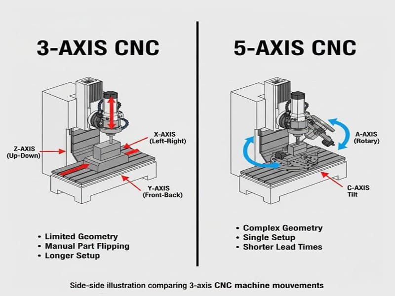
The question of 5 axis CNC machine vs 3 axis machining comes up constantly in custom part development — and the answer is rarely as simple as “more axes equals better parts.” The real question is whether the part geometry, tolerance requirements, and production volume justify the additional complexity and cost. A component that looks straightforward in CAD can become expensive and slow on a 3-axis machine if it needs five setups and three fixtures to complete. That same part might run in a single clamping on a 5-axis machine — but only if the CAM programming, tooling strategy, and process planning are executed correctly.
This article approaches the comparison as an engineering decision rather than a capability showcase. Both processes have clear strengths and well-defined limits. Understanding where each one delivers value — and where it doesn’t — is what allows engineers and procurement teams to specify the right process from the start, rather than discovering the wrong one during first-article inspection.
What Is a 5 Axis CNC Machine and How Does It Differ from 3 Axis?
Axis Configuration: Linear vs Rotational Freedom
Standard 3-axis machining moves the cutting tool along X, Y, and Z — left/right, front/back, and up/down. This is entirely adequate for prismatic parts, flat surfaces, and features accessible from one direction. The limitation appears when the part has angled faces, compound features, or geometry on multiple sides. Accessing those features requires re-clamping, a new datum setup, and another round of alignment verification. Each repositioning introduces potential error.
A 5-axis CNC machine adds two rotational axes — typically designated A, B, or C depending on machine configuration. These axes tilt and rotate the tool or the workpiece, allowing the cutting tool to approach the part from virtually any angle without physically relocating it. The result is fewer setups, a more consistent datum reference, and access to geometry that simply can’t be reached efficiently in 3-axis.
3+2 Indexed Machining vs Continuous 5-Axis Motion
Not every 5-axis operation runs all axes simultaneously. In indexed (3+2) machining, the rotary axes lock at a fixed angle while cutting proceeds along X, Y, and Z only. This approach handles angled holes, inclined planes, and multi-face features efficiently — with simpler programming than full simultaneous motion. Most 5-axis work in general CNC machining shops is actually 3+2 rather than continuous.
Continuous 5-axis machining moves all axes at once during the cut. This is the right approach for freeform surfaces, impeller blades, turbine components, and complex organic geometry where the tool orientation must change continuously to maintain consistent engagement. The programming complexity and verification requirements are higher, but for the right applications the surface quality and geometric accuracy improvements are significant.
| Возможности | 3-осевая обработка | 5-осевая обработка |
|---|---|---|
| Linear motion | X, Y, Z | X, Y, Z |
| Rotational motion | Нет | A/B/C (2 axes) |
| Typical setups | Multiple | Reduced / single |
| Complex surface access | Ограниченный | Отлично |
| Сложность программирования | Низкий | Средняя и высокая |
How a 5 Axis CNC Machine Improves Accuracy Over 3 Axis Machining
Accuracy in CNC machining isn’t just a machine specification — it’s a product of setup count, fixture consistency, datum strategy, and tool engagement conditions. This is where the accuracy comparison between 5-axis and 3-axis becomes concrete.
Single-Setup Machining and Error Accumulation
Every time a part is re-clamped in 3-axis machining, a new datum reference is introduced. Even with precision fixtures and careful alignment, each repositioning carries positioning uncertainty — typically 0.02–0.05 mm per re-setup on a well-maintained fixture. For a part requiring four setups to complete, that error can accumulate to the point where positional tolerances between features on different faces become impossible to hold reliably.
Five-axis machining eliminates most of these intermediate setups. When all critical features are machined from a single clamping, they share one datum reference throughout. For a multi-face aerospace bracket in aluminum 6061-T6 with positional tolerances of ±0.02 mm between hole patterns on two perpendicular faces, single-setup 5-axis machining is often the only reliable production method — not because the machine is more accurate in absolute terms, but because datum shift between setups is eliminated.
The same bracket in 316L stainless presents additional challenges. The material work-hardens under repeated cutting, and each setup reintroduces cutting force variations that can deflect thin walls or shift datum-sensitive features. Five-axis machining’s ability to complete the part in fewer operations reduces the number of times the workpiece is subjected to full setup loading and unloading — which matters in materials that respond to mechanical stress.
Tool Orientation and Dimensional Stability
In 3-axis machining, deep cavities and inclined surfaces often force long tool overhangs. A 12 mm end mill extended 60 mm from the holder deflects measurably under cutting forces — and that deflection translates directly into dimensional error at the part. For aluminum 6061-T6, this is manageable with conservative parameters. For 316L stainless at similar extension ratios, the cutting forces are higher and the process window for maintaining ±0.01 mm tolerances tightens significantly.
Five-axis machining addresses this by allowing the tool to approach features from a more favorable angle, shortening the effective reach and reducing deflection. Rather than plunging a long tool vertically into a deep feature, the part can be tilted so a shorter, stiffer tool accesses the same geometry at an angle. The result is better dimensional stability, more consistent surface finish, and reduced sensitivity to tool wear variation across a production run.
Surface Finish and Geometric Consistency
Freeform surfaces are where 3-axis machining struggles most and 5-axis machining excels most clearly. In 3-axis, scallop height on curved surfaces is controlled by stepover distance — tighter stepsover means better finish but longer cycle time. Continuous 5-axis machining can tilt the tool to maintain near-zero effective scallop height on compound curves, producing surface roughness of Ra 0.4–0.8 µm directly from machining, often eliminating hand polishing or secondary finishing steps.
For medical implants and orthopedic components where surface consistency affects both function and regulatory inspection, this capability has real production value beyond aesthetics.
Efficiency Comparison: Cycle Time, Tool Life, and Production Throughput
Efficiency in CNC machining isn’t just about cutting speed — it’s the combined outcome of setup time, tool life, non-cutting time, and downstream rework. All of these shift meaningfully between 3-axis and 5-axis processes.
Cycle Time: Where the Real Savings Come From
The most visible efficiency gain in 5-axis machining isn’t faster cutting — it’s reduced non-cutting time. In 3-axis machining, a complex part requiring four setups spends a significant fraction of its total production time being cleaned, repositioned, re-zeroed, and re-inspected between operations. For a precision aerospace component with a 45-minute cutting time per setup, the four setups might add 3–4 hours of handling and verification time per part.
Five-axis machining compresses this. A single clamping with one datum verification eliminates three of those four handling cycles. For low-to-medium volume production where setup time is a large fraction of total part time, this compression directly reduces lead time and per-part cost.
Toolpath efficiency also improves. Five-axis simultaneous motion allows shorter, more direct tool approaches to features. Fewer air cuts, fewer retracts, and continuous cutting motion reduce cycle time on the machine itself — particularly for contoured components where 3-axis toolpaths require many short segmented passes.
Tool Life: Controlled Engagement Angles
Tool wear in 3-axis machining is partly driven by geometry constraints. Long-reach tools engaged at suboptimal angles generate uneven chip loads and concentrate heat at specific points on the cutting edge. In difficult materials like 316L stainless or Ti-6Al-4V, this accelerates wear and makes tool change intervals difficult to predict.
Five-axis machining allows the tool to be oriented so cutting forces act along its strongest axis. Chip load distribution improves, heat spreads more evenly along the cutting edge, and wear patterns become predictable. For a Ti-6Al-4V aerospace component, switching from 3-axis with long tool extensions to 5-axis with optimized tool tilt can extend insert life by 30–50% — a meaningful reduction in tooling cost and unplanned machine stops on longer production runs.
The Programming vs Setup Trade-Off
Five-axis machining front-loads complexity into programming and simulation rather than into the shop floor. A 3-axis process might take 2 hours to program and 4 hours to set up across multiple operations. A 5-axis process for the same part might take 5 hours to program but only 45 minutes to set up and run. Over a 20-part batch, the 5-axis approach wins significantly on total time. For a single prototype, the equation is closer.
| Time Factor | 3-осевая обработка | 5-осевая обработка |
|---|---|---|
| Programming time | Коротко | Дольше |
| Setup time per part | Longer (multiple ops) | Short (single clamping) |
| Rework risk | Выше | Нижний |
| Идеально подходит для | High volume, simple parts | Low–medium volume, complex parts |
Cost Trade-Offs: When Is a 5 Axis CNC Machine Worth the Investment?
Evaluating 5-axis vs 3-axis on cost requires looking at total manufacturing cost per part — not hourly machine rate. The hourly rate for a 5-axis machine is higher, but that number doesn’t tell you what a part actually costs to produce.
Machine Cost, Programming, and Skill Requirements
A production 5-axis machining center carries a significantly higher capital cost than a 3-axis mill — typically 2–4× higher depending on travel, accuracy specification, and pallet system. CAM software licenses for 5-axis programming add further overhead, as do specialized post-processors and collision simulation environments. Programming a complex 5-axis operation requires engineers who understand multi-axis kinematics, tool orientation strategies, and how controller interpolation behavior affects actual cut geometry.
Three-axis machining benefits from simpler programming, a broader labor pool, and lower equipment cost. For straightforward prismatic parts produced in volume, these advantages are real and shouldn’t be dismissed in favor of five-axis capability that adds nothing to the part’s function.
When 5-Axis Delivers Lower Cost Per Part
The economic case for 5-axis machining strengthens as part complexity increases. A structural titanium bracket for an aerospace application requiring four setups on a 3-axis machine — each with its own fixture, datum verification, and partial inspection — might carry $180–220 in setup overhead per part at low volume. The same bracket on a 5-axis machine in a single clamping might reduce that overhead to $40–60, more than offsetting the higher hourly rate.
For prototype and EVT/DVT builds where per-part cost is dominated by setup and engineering time rather than material cost, 5-axis machining often produces faster delivery and lower total invoice cost despite higher machine rates.
Conversely, a simple aluminum 6061-T6 bracket with three parallel faces, standard hole patterns, and ±0.1 mm tolerances is efficiently produced on a 3-axis machine in two setups. Adding 5-axis complexity to this part adds programming time and machine cost without improving the outcome.
Hidden Costs: Rework, Inspection, and Scrap
Every additional setup in 3-axis machining is a scrap risk. A part that passes first-operation inspection but fails on positional tolerances between features after the second setup has consumed full machining time on both operations before the problem is discovered. In low-volume production of expensive material — titanium, Inconel, medical-grade stainless — this scrap risk has significant cost implications.
Five-axis machining reduces this risk by keeping the datum consistent throughout all cutting operations. Fewer setups mean fewer inspection hold points and less opportunity for cumulative error to push features out of tolerance before the problem is caught.
| Фактор решения | 3-осевая обработка | 5-осевая обработка |
|---|---|---|
| Геометрия детали | Simple, planar | Complex, multi-face |
| Объём производства | Средне-высокая | Низкий-средний |
| Сложность наладки | Multiple operations | Минимальный |
| Rework risk | Выше | Нижний |
| Total cost advantage | Simple high-volume parts | Complex low-volume parts |
Material and Cutting Strategy Differences Between 5-Axis and 3-Axis
Material behavior under cutting loads amplifies the process differences between 3-axis and 5-axis machining. For standard aluminum alloys and free-machining materials, the differences are manageable. For difficult materials and deformation-sensitive geometries, cutting strategy has a direct impact on dimensional stability and scrap rate.
Titanium, Stainless Steel, and High-Temperature Alloys
Ti-6Al-4V and 316L stainless share two characteristics that create problems in 3-axis machining: low thermal conductivity and high cutting forces. In 3-axis operations with long tool overhangs, heat concentrates at the tool tip and cutting forces fluctuate as the engagement angle changes across a complex surface. For Ti-6Al-4V, this combination risks work hardening and thermal distortion. For 316L, work hardening from inconsistent chip loads between passes progressively hardens the material surface, making finish operations harder and dimensional control less predictable.
Five-axis machining addresses both issues by allowing the tool to maintain a consistent engagement angle throughout the cut. For Ti-6Al-4V aerospace components, this means cutting forces stay aligned with the tool’s axial direction — the orientation where carbide tools are strongest. Recommended parameters in 5-axis Ti-6Al-4V machining typically run 40–60 m/min surface speed with 0.05–0.10 mm/tooth chip load, lower than aluminum but sustainable over longer tool life due to the improved engagement consistency.
For 316L stainless in 5-axis operations, maintaining consistent chip load prevents the work-hardening buildup that turns finishing passes into roughing operations. Typical 5-axis 316L parameters run 80–120 m/min surface speed with flood coolant and 0.08–0.15 mm/tooth chip load — achievable with stable tool orientation but difficult to maintain consistently in multi-setup 3-axis operations.
Toolpath Optimization for Difficult Materials
Advanced toolpath strategies further differentiate 5-axis from 3-axis in difficult materials. Trochoidal milling and constant-engagement toolpaths — strategies that maintain uniform chip load throughout the cut — are practical in 5-axis machining because the tool can adjust orientation to keep engagement consistent even on complex surfaces. In 3-axis, these strategies are limited to 2D profiles and pockets because tool orientation is fixed.
Continuously variable tool tilt in 5-axis machining also enables better chip evacuation on deep features. Chips clear the cutting zone rather than being re-cut, which reduces heat buildup, extends tool life, and produces more consistent surface finish on the final pass.
Thin-Wall and Flexible Structures
Thin-wall components — ribs below 2 mm, walls with height-to-thickness ratios above 8:1, and complex lightweight structures — are among the most difficult 3-axis applications. Lateral cutting forces deflect thin walls during machining, and the part springs back to a different position when unclamped. The dimensional error shows up at inspection, not during cutting.
Five-axis machining reduces this problem by directing cutting forces toward the part’s structurally supported sections. The tool can approach from above or at an angle that loads the wall in compression rather than bending. This approach reduces elastic deflection during cutting and improves dimensional repeatability at final inspection — particularly valuable for aerospace rib structures and medical implant geometries where wall thickness tolerances are tight.
| Material / Feature | 3-Axis Strategy | 5-Axis Strategy |
|---|---|---|
| Ti-6Al-4V | Conservative, long tool extensions | Optimized tilt, stable chip load |
| Нержавеющая сталь 316L | Risk of work hardening | Controlled engagement angle |
| Thin-wall structures | Multiple light passes, deflection risk | Force-directed, compression-loaded cutting |
| Freeform surfaces | Segmented toolpaths, scalloping | Continuous tool tilt, consistent finish |
Programming and CAM Considerations: Why 5-Axis Requires More Engineering Investment
The accuracy and efficiency advantages of 5-axis machining don’t come automatically. They come from careful programming, thorough simulation, and experienced process planning. Without those elements, a 5-axis machine produces parts no better than what a 3-axis machine would have made — at higher cost.
CAM Software Requirements for 5-Axis Operations
Five-axis CAM programming is fundamentally different from 3-axis. The software must calculate continuous tool orientation in three-dimensional space, manage the rotary axis limits of the specific machine configuration, and produce smooth motion transitions across complex surfaces. Post-processor accuracy is critical — a minor mismatch between the CAM output and the machine’s kinematic model causes positioning errors that show up as surface defects or dimensional deviations.
Collision avoidance logic is another layer of complexity. In 5-axis machining, the tool, holder, spindle, rotary table, fixture, and machine structure can all potentially interfere as the machine tilts and rotates. CAM systems must model the complete machine environment and verify clearance at every point in the toolpath — a computation-intensive process that takes time but prevents costly on-machine collisions.
Simulation and Verification Before Cutting
Virtual verification is non-negotiable for 5-axis programs, particularly simultaneous operations. Full machine simulation — not just toolpath visualization — checks for collisions, over-travel conditions, and rapid axis reversals that could cause surface marks or structural concerns. This step adds programming time but dramatically reduces first-article scrap risk.
For a complex aerospace component in Ti-6Al-4V, the cost of a simulation-prevented collision is zero. The cost of discovering the same collision on the machine — with a damaged spindle, crashed fixture, and scrapped $800 titanium billet — is immediately obvious. Experienced shops treat simulation as mandatory, not optional.
Process Planning as the Critical Skill
Ultimately, 5-axis machining success depends on engineering judgment before the program is written. Tool selection, approach angles, feature sequencing, and fixture design must all be resolved at the planning stage. The best 5-axis machine in the world, running a poorly planned program, produces mediocre results. A well-planned process on a mid-range 5-axis machine often outperforms a premium machine running an unoptimized program.
The standard 5-axis workflow reinforces this:
CAD model → 5-axis CAM programming → Full machine simulation → Dry run verification → Production machining
Each step is an engineering checkpoint, not just a software operation.
Typical Applications Where 5-Axis Outperforms 3-Axis Machining
Several application categories consistently demonstrate where 5-axis capability provides measurable production value — not just theoretical flexibility.
Aerospace Structural and Engine Components
Aerospace brackets, housings, blisks, and structural ribs combine tight geometric tolerances, multi-face features, and hard-to-machine alloys. A titanium structural bracket with hole patterns on three orthogonal faces and positional tolerances of ±0.015 mm between them represents a straightforward 5-axis application. Running it on a 3-axis machine requires at minimum three setups — each introducing its own datum error and each consuming time in fixture changeover and re-inspection.
Beyond structural parts, impellers and blisks require continuous 5-axis motion to machine blade profiles cleanly. Three-axis machining of these surfaces is practically impossible without accepting surface quality well below aerospace requirements. Five-axis machining with optimized tilt angles produces the smooth, accurate blade surfaces these components require directly from the machine.
Medical Implants and Precision Devices
Orthopedic implants — hip stems, knee tibial trays, spinal cages — combine complex organic geometry with tight dimensional tolerances and stringent surface finish requirements. Ra values of 0.4–0.8 µm on bearing surfaces, and positional tolerances of ±0.05 mm on fixation hole patterns, are typical requirements that drive both process selection and inspection strategy.
Continuous 5-axis machining produces these surfaces with consistent tool engagement, reducing the micro-irregularities that hand polishing introduces. Fewer setups also simplify the production audit trail — in regulated medical manufacturing, a clear and minimal setup sequence makes process validation significantly more straightforward.
Complex Automotive and Robotics Components
Automotive prototype components and motorsport parts frequently push design boundaries — compact packaging, integrated functions, compound geometry that would require design compromises if constrained to 3-axis manufacturing. Five-axis machining supports these geometries without forcing the designer to add clearance for 3-axis tool access, which reduces part weight and simplifies assembly.
For robotics, structural arm links and end-effector housings often combine mounting bores on multiple faces with tight perpendicularity requirements. Single-setup 5-axis machining holds these relationships more reliably than multi-setup 3-axis, and the faster turnaround benefits the iterative development cycles common in robotics.
| Область применения | Основные вызовы | 5-Axis Advantage |
|---|---|---|
| Аэрокосмические конструкции | Tight GD&T, multi-face, hard alloys | Single-setup accuracy, force control |
| Медицинские изделия | Surface finish, repeatability | Consistent freeform machining |
| Automotive / robotics | Complex geometry, fast iteration | Reduced setups, design freedom |
How to Decide: A Practical Selection Guide
The right process choice depends on matching part requirements to process capability — not on defaulting to the most advanced option available.
Five-axis machining makes sense when:
- The part has features on multiple faces with tight geometric relationships (positional tolerances across setups)
- Single-setup datum consistency is required to meet tolerance
- The material is difficult to machine and benefits from controlled tool orientation (Ti-6Al-4V, 316L, Inconel)
- Volume is low-to-medium and setup time is a significant fraction of total part cost
- Freeform surfaces require continuous tool orientation for surface quality
Three-axis machining remains the right choice when:
- Part geometry is prismatic with features accessible from one or two directions
- Tolerances are achievable within the setup repeatability of standard fixtures (±0.05 mm or looser)
- Production volume is high and the process is stable and well-characterized
- Programming time and CAM complexity are constraints
- Raw material is free-machining and tool engagement is predictable at standard parameters
| Вопрос | Если да → |
|---|---|
| Multi-face features with tight GD&T? | Consider 5-axis |
| Single-setup datum consistency required? | Consider 5-axis |
| Simple geometry, high volume? | Consider 3-axis |
| Programming time is a major constraint? | Consider 3-axis |
| Difficult material with force control requirements? | Consider 5-axis |
Заключение
Five-axis CNC machining and 3-axis machining aren’t competing technologies — they’re tools suited to different manufacturing problems. Three-axis machining remains highly efficient for prismatic parts, high-volume production, and geometries where tolerance requirements fit comfortably within multi-setup process capability. Five-axis machining earns its place when part geometry, tolerance relationships between features, or material behavior exceed what linear-axis workflows can deliver reliably.
The practical decision comes down to total manufacturing cost and process risk, not machine sophistication. For complex low-volume parts — aerospace brackets, medical implants, precision fittings in difficult materials — five-axis machining reduces setup overhead, improves datum consistency, and lowers scrap risk enough to justify the higher programming and equipment cost. For high-volume prismatic parts with straightforward tolerances, a well-optimized 3-axis process consistently delivers better economics. Getting this choice right at the design stage prevents the much more expensive discovery of the wrong choice at first article.
Часто задаваемые вопросы
Is a 5-axis CNC machine always more accurate than 3-axis machining?
Not automatically. Accuracy depends on the full process — setup strategy, fixture design, and datum consistency — not just axis count. Five-axis machining improves accuracy primarily by reducing setup-to-setup datum error on multi-face parts. For simple single-face parts, a well-designed 3-axis process with proper fixtures achieves equivalent accuracy at lower cost.
When is 3-axis machining still the better choice?
Three-axis machining remains ideal for prismatic parts with simple geometry, features accessible from one or two directions, and high-volume production where the process is stable and well-characterized. Lower programming effort, faster setup for repeat jobs, and lower hourly rates often produce a better total cost per part when complexity is limited.
How much more expensive is 5-axis machining per part?
Machine hourly rates for 5-axis are typically 30–60% higher than 3-axis. However, per-part cost can be comparable or lower when 5-axis machining reduces fixture count, setup time, and rework. Always compare total manufacturing cost — programming plus setup plus machining plus rework — not hourly rate alone.
Can 3+2 indexed machining replace continuous 5-axis?
For many applications, yes. Indexed 3+2 machining handles angled holes, inclined planes, and multi-face prismatic features with simpler programming and lower risk than full simultaneous motion. Continuous 5-axis is specifically needed for freeform surfaces, smooth transitions across compound curves, and components where constant tool orientation is required throughout the cut.
Does production volume affect the ROI of a 5-axis CNC machine?
Significantly. ROI is strongest in low-to-medium volume, high-mix production where setup reduction and first-pass yield matter most. For high-volume simple parts, optimized 3-axis machining typically delivers better economics. For prototypes, EVT/DVT builds, and complex short runs, 5-axis often provides faster turnaround, lower total cost, and better quality outcomes.


