
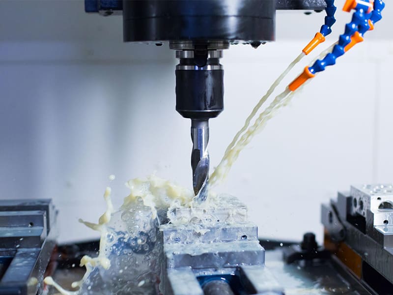
CNC frezeleme, dijital tasarımları hassas ve tekrarlanabilir parçalara dönüştüren temel bir üretim sürecidir. Esneklik, doğruluk ve hızlı teslim süresi sunduğu için prototipleme, tasarım doğrulama ve düşük ila orta hacimli üretimde yaygın olarak kullanılır.
Manuel frezeleme ve diğer işleme süreçleriyle karşılaştırıldığında, CNC frezeleme dar toleranslara ve tutarlı kaliteye sahip karmaşık geometrilerin üretiminde üstündür. Prototipten üretime sorunsuz geçiş yapabilme yeteneği, onu modern hassas üretimin temel taşı haline getirir.
CNC Frezeleme Nedir ve Gerçekte Nasıl Çalışır?
CNC Frezelemenin Tanımı
CNC frezeleme bir eksiltici üretim bir bilgisayar sayısal kontrol (CNC) sistemi tarafından kontrol edilen döner kesici takım kullanılarak katı bir iş parçasından malzemenin çıkarıldığı bir süreçtir. Makine, CAD/CAM verilerinden türetilen programlanmış takım yollarını izler ve gerekli geometriyi oluşturmak için takımı birden fazla eksen (X, Y, Z ve bazen daha fazlası) boyunca hassas bir şekilde hareket ettirir. Mühendislik açısından, CNC frezeleme üç temel unsurla tanımlanır: dijital kontrol, döner kesici takımlar ve yüksek düzeyde tekrarlanabilir hareket—bunlar birlikte manuel olarak elde edilmesi zor veya imkansız olan dar toleransları ve karmaşık geometrileri mümkün kılar.
CNC Frezeleme ile Manuel Frezeleme Karşılaştırması
CNC frezeleme ile manuel frezeleme arasındaki temel fark kontrol ve tutarlılıktır. Manuel frezelemede doğruluk büyük ölçüde operatör becerisine bağlıdır ve tekrarlanabilirlik partiler arasında bozulur. CNC frezeleme, manuel el çarklarını servo tahrikli eksenlerle değiştirerek mikron düzeyinde konumlandırma doğruluğu ve ilk parçadan bininci parçaya kadar aynı sonuçları sağlar. Otomasyon ayrıca gözetimsiz işlemeyi, öngörülebilir çevrim sürelerini ve istikrarlı kaliteyi mümkün kılar—hassas parça üretimi için kritik öneme sahiptir.
CNC Frezeleme ile CNC Tornalama Karşılaştırması
CNC frezeleme ve CNC tornalama, CNC işleme süreci içinde farklı ancak tamamlayıcı roller üstlenir. Frezeleme, iş parçasını sabit tutarken takım döner ve hareket eder; bu da düz yüzeyler, cepler ve karmaşık 3D özelliklere sahip prizmatik parçalar için idealdir. Tornalama ise iş parçasının kendisini döndürür, bu da miller, pimler ve dönel simetrik bileşenler için daha verimlidir.
Frezeleme ile Tornalama — Mühendislik Karşılaştırması
| Aspect | CNC Frezeleme | CNC Torna |
| Birincil hareket | Döner takım | Döner iş parçası |
| Tipik geometriler | Kutular, muhafazalar, plakalar | Miller, burçlar, pimler |
| Özellik kabiliyeti | Cepler, kanallar, konturlar | Çaplar, konikler, oluklar |
| Tasarım esnekliği | Çok yüksek | Orta (eksenel simetrik) |
Bu farklılıkları anlamak, mühendislerin ve alıcıların hassas parça üretimi için en verimli süreci—veya doğru kombinasyonu—seçmesine yardımcı olur.
CNC Frezeleme Süreci: Tasarımdan Bitmiş Parçaya
CAD Tasarımı ve DFM Hususları
CNC frezeleme süreci, CAD tasarım aşamasında, başlar; burada mühendislik kararları üretilebilirliği, maliyeti ve teslim süresini doğrudan etkiler. DFM (Üretim için Tasarım) perspektifinden, özellikler frezeleme gerçekleri göz önünde bulundurularak tasarlanmalıdır. Temel hususlar şunları içerir: minimum duvar kalınlığı (titreşim ve deformasyonu önlemek için), iç köşe yarıçapları (parmak frezeler keskin iç köşeler oluşturamaz) ve takım erişilebilirliği (derin cepler veya dar kanallar, rijitliği azaltan uzun takımlar gerektirebilir). İyi hazırlanmış CAD modelleri, CAM karmaşıklığını azaltır ve sonraki işleme risklerini en aza indirir.
CAM Programlama ve Takım Yolu Planlaması
Tasarım kesinleştirildikten sonra, CAD modeli takım yollarının oluşturulduğu CAM yazılımı, içine aktarılır. Bu aşama, nasıl parçanın nasıl işleneceğini tanımlar. Mühendisler tipik olarak operasyonları kaba işleme (yüksek malzeme kaldırma oranı, kararlı kesme) ve finiş işleme (low material removal, high surface quality). Toolpaths may be 2D (profiles, pockets), 3D (freeform surfaces), or 3+2 indexed machining, where the part is repositioned between operations. Proper CAM planning balances cutting efficiency, tool life, surface finish, and dimensional accuracy.
Machine Setup & Fixturing
Before cutting begins, the workpiece must be accurately mounted on the machine. Referans seçimi is critical: all dimensions and tolerances are referenced from these datums during machining and inspection. Fixture stability directly affects precision—insufficient clamping rigidity can lead to chatter, dimensional drift, or tool breakage. In production environments, repeatable fixturing also ensures consistency across multiple parts and setups, especially for multi-face CNC milling operations.
Machining Execution & In-Process Control
During machining, the CNC system executes programmed toolpaths while monitoring spindle speed, feed rate, and axis motion. In-process control may include tool length compensation, wear offsets, and probing cycles to verify critical dimensions mid-process.
This closed-loop approach allows CNC milling to consistently produce precision parts that match the original CAD intent, even as designs move from prototyping to batch production.
Typical CNC Milling Workflow CAD Design → CAM Programming → Machine Setup & Fixturing → Machining → Inspection
Understanding this end-to-end workflow helps engineers and procurement teams evaluate lead time, cost drivers, and quality risks in precision parts manufacturing.
CNC Milling Machines and Axis Configurations
Core Machine Components
Regardless of axis count, all CNC milling machines share several critical components that determine accuracy and reliability. The iş mili provides rotational power and stiffness for cutting, directly influencing surface finish and tool life. The tool holder connects the cutting tool to the spindle and must maintain concentricity under load to avoid runout. The control system interprets CNC programs and coordinates axis motion with spindle speed and feed rate, forming the “brain” of the machine. Meanwhile, the coolant system manages heat, chip evacuation, and tool wear—especially important when machining aluminum, steel, or heat-sensitive alloys.
3-Axis, 4-Axis, and 5-Axis CNC Milling
Axis configuration defines a machine’s manufacturing capability. 3-axis CNC milling (X, Y, Z) is the industry baseline and suits most prismatic parts with features accessible from one or two sides. Adding a 4th axis (rotational) enables indexed machining around a single rotation, improving efficiency for parts with features on multiple faces. 5-axis CNC milling introduces two rotational axes, allowing the tool to approach the part from almost any direction—ideal for complex geometries, deep cavities, and reduced setups.
Axis Capability Comparison
| Eksen Tipi | Motion Capability | Tipik Uygulamalar |
| 3 eksen | Linear X/Y/Z | Plakalar, muhafazalar, braketler |
| 4 eksen | 3-axis + rotation | Multi-face parts, indexing |
| 5-axis | 3-axis + dual rotation | Complex surfaces, aerospace |
Dikey ve Yatay Freze Makineleri
Dikey freze makineleri are the most common in precision parts manufacturing due to their flexibility and ease of setup. They are well suited for prototypes and small to medium batch production. Yatay freze makineleri, with side-mounted spindles, offer superior chip evacuation, longer tool life, and higher material removal rates for production environments. While less common for prototypes, they excel in high-volume CNC milling where efficiency and stability are priorities.
Selecting the right machine configuration helps engineers balance complexity, cost, and production efficiency in CNC milling projects.
Common CNC Milling Operations Explained
Face Milling & Pocket Milling
Yüzey frezeleme involves the cutting tool facing the workpiece, with the primary objective being the removal of material from flat surfaces. It’s most commonly used for creating flat, smooth surfaces on parts like plates, panels, or brackets. The cutting edges on the tool engage with the surface, and the material is progressively removed. Key considerations in face milling include tool material, spindle speed, and feed rate, which directly affect surface finish quality and cutting efficiency.
Pocket milling is a type of milling operation where the tool removes material from the interior of a part to create cavities or pockets. This operation is typically used when producing parts with intricate internal shapes, such as housings or containers. The pocket’s depth, size, and complexity determine the toolpath strategy. Special attention must be paid to tool engagement, as deeper pockets can lead to excessive tool wear or even failure.
Slot, Profile, and Contour Milling
Yuva frezeleme is focused on cutting narrow channels or grooves within a part. It’s common in industries where precision slots are needed for assembly or functionality, such as creating slots for rails, fasteners, or electrical wiring.
Profile milling is a process where the tool cuts along the contour of a shape, often along the edges or along a specific outline. This is typically used to create shapes like logos, designs, or other custom patterns on parts. Both slot ve profile milling operations require precise control over the cutter’s path to achieve tight tolerances.
Contour milling, similar to profile milling, involves cutting around the part’s outline but can also include curved or angled surfaces. It’s essential for creating complex 2D and 3D shapes, especially in precision engineering fields such as automotive and aerospace.
3D Surface & Complex Geometry Milling
3D surface milling is employed when complex, freeform surfaces need to be machined, which can’t be achieved with conventional 2D milling operations. Examples include turbine blades, molds, or complex automotive parts. This operation requires 5-axis milling machines, allowing for tool rotation along multiple axes to approach the part from various angles. Toolpath generation is highly complex and needs to be optimized for efficient material removal and minimal tool wear.
Machining these complex geometries demands careful consideration of tool selection, feed rates, and machine calibration to ensure precision and avoid damaging delicate features.
High-Efficiency & Adaptive Milling
High-efficiency milling (HEM) is a strategy designed to maximize the material removal rate (MRR) while maintaining the desired part geometry. HEM techniques involve using larger stepovers and higher cutting speeds with lighter cuts to keep the tool engagement at an optimal level. This process reduces cutting forces, thus improving tool life and productivity. It’s particularly effective when machining harder materials like titanium or stainless steel.
Adaptive milling involves adjusting machining parameters dynamically based on real-time feedback from the part or tool. This approach helps in dealing with variations in material hardness or part geometry. Adaptive milling is often employed in situations where there’s a high level of uncertainty in the material consistency, or when producing parts in high volumes.
CNC Milling Operations Comparison
| İşlem Türü | Tipik Uygulamalar | Design Considerations |
| Yüzey Frezeleme | Flat surfaces, panel machining | Tool choice, surface finish |
| Pocket Milling | Cavities, internal features | Toolpath complexity, engagement |
| Yuva Frezeleme | Precision slots, grooves | Tolerance, cutter path planning |
| Profile Milling | Shape outlines, custom patterns | Precision, cutter radius |
| 3D Surface Milling | Complex geometries, mold making | Toolpath generation, machine setup |
| High-Efficiency Milling | High-volume machining | Speed, tool wear, material removal rate |
By understanding and selecting the correct milling operation, manufacturers can optimize CNC machining processes for both efficiency and precision.
Cutting Parameters and Machining Performance
In CNC milling, achieving optimal efficiency, precision, and part quality depends on controlling various kesme parametreleri. These parameters not only affect the machining time and cost but also have a direct impact on the yüzey bitirme, tool life, ve cutting efficiency. Understanding how to adjust these parameters to suit specific materials and part designs is crucial for engineers, machinists, and manufacturers aiming for high-quality outputs at competitive costs.
Cutting Speed, Feed Rate & Depth of Cut
These three primary cutting parameters — cutting speed, besleme hızı, ve depth of cut — significantly influence both machining efficiency ve surface quality.
-
Cutting Speed (V_c): The speed at which the tool cuts through the material. Increasing the cutting speed generally improves material removal rates (MRR), but it also results in higher heat generation. Optimal cutting speed ensures tool life is maximized while balancing material removal efficiency.
-
Feed Rate (F): The rate at which the tool moves through the material. Higher feed rates increase material removal rates but can lead to lower surface quality and faster tool wear if not carefully controlled.
-
Depth of Cut (d): The depth of material that is cut in one pass. A deeper cut improves efficiency by increasing the volume of material removed per pass, but it can increase tool wear and heat generation, especially for harder materials.
| Parametre | Effect on Efficiency | Effect on Surface Finish | Effect on Tool Life |
| Kesme Hızı | Increased MRR with higher speed | Can lead to rougher surfaces if too high | Too high can reduce tool life due to excessive heat |
| İlerleme Hızı | Higher rate increases MRR | Can reduce finish quality if too high | Higher rates can increase tool wear |
| Kesme Derinliği | Deeper cuts increase MRR | Can create rougher surfaces at high depth | Deeper cuts can lead to higher tool wear and heat buildup |
By carefully balancing these parameters, manufacturers can achieve a high material removal rate (MRR) while ensuring that surface finishes remain within the required tolerances.
Tool Materials and Coatings
Bu malzeme ve coating of the cutting tool play a critical role in machining performance, especially in terms of tool life, heat resistance, ve cutting efficiency.
-
Carbide Tools: Carbide is one of the most common tool materials in CNC milling. It is known for its high hardness ve heat resistance, which makes it ideal for machining harder materials such as steel and titanium. Carbide tools generally last longer, but they can be brittle and susceptible to chipping under excessive impact.
-
Kaplamalar: Tools coated with materials like TiAlN (Titanium Aluminum Nitride) ve DLC (Diamond-Like Carbon) are used to enhance performance. These coatings provide heat resistance, reduce friction, and improve wear resistance, all of which extend tool life and improve surface quality. TiAlN is particularly effective for high-speed cutting operations, while DLC coatings are often used for reducing friction in applications requiring extremely smooth surfaces.
| Tool Material/Coating | Key Benefits | Best Suited For | Sınırlamalar |
| Karbür | High hardness, wear resistance | Harder metals, high-speed machining | Brittle, prone to chipping |
| TiAlN Coating | Excellent heat resistance, longer tool life | High-speed machining of hard materials | Can be more expensive |
| DLC Coating | Low friction, improved surface finish | Precision parts, machining of soft materials | Costly for some applications |
Tool Life, Chip Load & Surface Finish
Tool life and surface finish are intertwined factors in CNC milling, and they are both directly impacted by çip yükü ve kesme parametreleri.
-
Tool Life: Overloading a tool or using too high a feed rate, cutting speed, or depth of cut can cause premature wear or failure of the tool. Proper çip yükü, which is the amount of material the tool removes with each pass, is crucial for maintaining tool life. Higher chip loads reduce wear but can increase heat generation, which affects the tool’s lifespan.
-
Çip Yükü: This parameter represents the thickness of the chip removed by each tooth of the tool. It is essential to match the chip load to the cutting material to avoid excessive force on the tool, which could lead to breakage or deformation.
-
Yüzey İşlemi: High cutting speeds and small feed rates tend to provide better surface finishes by creating smoother cuts. If the feed rate is too high, the cutting tool leaves larger grooves and marks, leading to a rougher surface. On the other hand, proper tool geometry and chip load will provide a finer finish with less post-processing required.
| Parametre | Effect on Tool Life | Effect on Surface Finish | Effect on Chip Load |
| İlerleme Hızı | Higher rates reduce tool life if excessive | Higher feed rates decrease surface quality | Large chip load can improve efficiency but worsen surface finish |
| Kesme Hızı | Optimal speed prolongs tool life | Higher speed can improve surface finish if controlled | Higher speed can increase cutting forces, affecting chip load |
| Çip Yükü | Higher chip loads increase tool wear | Large chips can lead to a rougher finish | Correct chip load improves machining efficiency and tool life |
Thermal Effects & Vibration Control
Thermal effects and vibrations are some of the most critical factors affecting cutting performance ve tool life.
-
Thermal Effects: Excessive heat generated during cutting can significantly impact both the tool life ve workpiece. Bu cutting temperature must be managed by adjusting cutting speeds and feed rates and using proper coolant to ensure that the material does not soften or deform, which can impact the dimensional accuracy of the finished part.
-
Vibration Control: Vibrations during machining, commonly referred to as chatter, can reduce both tool life and surface quality. Chatter occurs when the cutting forces cause the tool to oscillate, leading to uneven cuts and potentially damaging the workpiece. It can be mitigated by adjusting cutting parameters, using stable tooling setups, and ensuring proper fixturing.
| Parametre | Effect on Tool Life | Effect on Surface Finish | Effect on Vibration |
| Kesme Hızı | Excessive speed leads to high heat and tool wear | Improper speed creates uneven cuts | High speed may lead to increased chatter |
| İlerleme Hızı | Can generate excessive heat if too high | Higher feed can lead to poor surface finish | Higher feed can exacerbate vibrations |
| Takım Geometrisi | Proper tool geometry reduces heat buildup | Fine geometry leads to smooth cuts | Incorrect geometry can increase vibration risks |
In CNC milling, achieving the best machining results requires a delicate balance of these cutting parameters. By understanding and controlling cutting speed, besleme hızı, tool materials, ve thermal management, manufacturers can ensure high-efficiency machining ve superior surface finishes while optimizing tool life. These optimizations are key to reducing costs and ensuring the longevity and quality of the produced parts.
Materials Suitable for CNC Milling
One of the main strengths of CNC milling is its broad material compatibility. From easy-to-cut aluminum to high-performance polymers and difficult exotic alloys, CNC milling can accommodate a wide range of engineering materials—provided the tooling, parameters, and process strategy are correctly selected.
Common Metals
Metaller are the most frequently CNC-milled materials in precision parts manufacturing, especially for structural and functional components.
-
Alüminyum (e.g., 6061, 7075): Excellent machinability, low cutting forces, and high material removal rates make aluminum ideal for prototypes and production parts. It is widely used in aerospace, electronics housings, and mechanical assemblies.
-
Karbon Çelik: Offers high strength at relatively low material cost. Machinability varies by grade and heat treatment; cutting forces and tool wear are higher than aluminum.
-
Paslanmaz Çelik (e.g., 304, 316): Provides corrosion resistance but introduces challenges such as work hardening and heat retention, requiring conservative feeds and rigid setups.
-
Pirinç: One of the easiest metals to machine, producing clean chips and excellent surface finishes—commonly used for fittings, connectors, and precision components.
Plastikler & Mühendislik Polimerleri
CNC milling is also widely used for plastics and polymers, especially when tight tolerances or low-volume production are required.
-
ABS: Easy to machine and cost-effective, suitable for housings and functional prototypes.
-
POM (Asetal/Delrin): Excellent dimensional stability and low friction, ideal for gears and precision mechanical parts.
-
PEEK: A high-performance polymer with excellent chemical and thermal resistance, often used in medical, aerospace, and semiconductor applications. Machining requires sharp tools and controlled heat input.
Hard-to-Machine & Exotic Materials
Some applications demand materials with extreme properties, but these come with increased machining complexity.
-
Titanyum alaşımları: High strength-to-weight ratio and corrosion resistance, but low thermal conductivity leads to heat concentration and rapid tool wear.
-
Nickel-based alloys (e.g., Inconel): Designed for high-temperature environments, extremely demanding on tools and machines.
-
Hardened steels: Require rigid machines, coated carbide tools, and reduced cutting parameters.
CNC Milling Material Selection Overview
| Malzeme | İşleme Zorluğu | Typical Challenges | Recommended Tooling |
| Alüminyum | Düşük | Çipin çıkarılması | Carbide, polished flutes |
| Karbon Çelik | Orta | Cutting force, wear | Kaplamalı karbür |
| Paslanmaz Çelik | Orta-Yüksek | Work hardening, heat | TiAlN-coated carbide |
| Pirinç | Çok Düşük | Minimal | Carbide or HSS |
| ABS / POM | Düşük | Melting, burrs | Keskin karbür |
| PEEK | Orta | Isı hassasiyeti | Sharp carbide, low heat |
| Titanyum | Yüksek | Heat, tool wear | Premium coated carbide |
Understanding material behavior helps engineers and buyers anticipate cost, lead time, and risk in CNC milling projects. Selecting the right combination of material, tooling, and process strategy is essential for consistent quality in precision parts manufacturing.
Tolerances, Quality Control, and Inspection
Achieving reliable accuracy in CNC milling depends not only on machine capability, but also on how tolerances are specified, controlled, and verified throughout production. Clear tolerance definition and appropriate inspection methods are essential to avoid scrap, rework, and supplier–customer disputes.
Typical Tolerances in CNC Milling
In standard CNC milling operations, general tolerances of ±0.05 mm (±0.002 in) are commonly achievable without special processes. With optimized tooling, stable fixturing, and controlled environments, tighter tolerances such as ±0.01 mm (±0.0004 in) are realistic for critical features. However, tighter tolerances directly increase machining time, inspection effort, and cost. From an engineering perspective, tolerances should reflect functional requirements, not default “tight as possible” values. Over-specifying tolerances is one of the most common cost drivers in precision parts manufacturing.
GD&T Considerations
Geometric Dimensioning and Tolerancing (GD&T) plays a key role in CNC milling by defining form, orientation, and positional requirements, not just size. Features such as flatness, perpendicularity, and position often matter more than linear dimensions for part function and assembly. Proper datum selection is critical: datums should reflect how the part is fixtured during machining and how it is referenced during inspection. Misaligned datums frequently lead to parts that “meet the drawing” but fail in real assemblies.
Inspection & Measurement Methods
Inspection closes the loop between design intent and manufacturing reality. For milled parts, common methods include:
-
CMM (Koordinat Ölçüm Makinesi): Provides high-accuracy, repeatable measurement of complex geometries and GD&T features. Best suited for precision and multi-feature inspection.
-
Gauges and Hand Tools: Calipers, micrometers, height gauges, and go/no-go gauges are efficient for quick checks and in-process control.
-
İşlem İçi Probing: Many CNC milling machines use touch probes to verify datums and critical dimensions during machining, reducing cumulative error.
Effective quality control in CNC milling is not about measuring everything—it is about measuring the right features, at the right time, with the right method. This approach ensures consistency, controls cost, and builds confidence for engineers and procurement teams alike.
Applications of CNC Milling in Precision Manufacturing
CNC milling is widely adopted across industries where dimensional accuracy, repeatability, and material versatility are critical. Its ability to produce complex geometries with tight tolerances makes it a foundational process in modern precision machining.
Aerospace & Automotive
İçinde aerospace and automotive sectors, CNC milling is used to manufacture both structural and functional components that must meet strict performance and safety standards. Typical applications include brackets, housings, engine components, transmission parts, and fixtures. Aerospace parts often require high-strength aluminum alloys, titanium, or stainless steel, combined with tight tolerances and full traceability. Automotive applications balance precision with cost efficiency, using CNC milling for prototyping, tooling, and low- to mid-volume production where flexibility is essential.
Medical Devices & Precision Components
Bu medical industry relies heavily on CNC milling for precision components used in surgical instruments, diagnostic equipment, implants, and device housings. These parts often feature small dimensions, complex contours, and demanding surface finish requirements. Materials such as stainless steel, titanium, and high-performance polymers (e.g., PEEK) are common, and machining processes must support biocompatibility and consistent quality. CNC milling enables controlled, repeatable production that aligns with regulatory and inspection requirements in medical manufacturing.
Electronics, Tooling & Prototyping
İçinde electronics and industrial tooling, CNC milling is frequently used to produce enclosures, heat sinks, connectors, jigs, fixtures, and mold components. Aluminum and copper alloys are popular due to their thermal and electrical properties. For prototyping and new product development, CNC milling bridges the gap between design and production. Engineers can validate form, fit, and function using production-grade materials before committing to tooling or mass manufacturing.
Across these applications, CNC milling supports a common goal: transforming digital designs into accurate, functional parts with predictable quality. This versatility is why CNC milling remains a core technology in precision manufacturing worldwide.
Cost, Lead Time, and Process Selection
For engineers and buyers, CNC milling decisions are rarely based on capability alone. Cost, lead time, and process fit ultimately determine whether CNC milling is the right manufacturing choice for a given part.
What Drives CNC Milling Cost
CNC milling cost is primarily influenced by a combination of malzeme, machining time, ve complexity. Harder materials increase tool wear and cycle time. Tight tolerances and fine surface finishes require slower feeds, additional finishing passes, and more inspection effort. Other cost drivers include the number of setups, fixture complexity, and whether multi-axis machining is required. From a procurement perspective, simplifying geometry and avoiding unnecessary tolerance tightness often delivers the largest cost savings.
CNC Milling vs Turning vs EDM
Selecting the right process is critical for cost efficiency:
-
CNC Frezeleme is ideal for prismatic parts, pockets, slots, and complex 3D geometries. It offers the greatest design flexibility but can be more expensive for purely rotational features.
-
CNC Torna is more cost-effective for shafts, pins, and cylindrical components due to faster cycle times and simpler setups.
-
EDM (Elektriksel Deşarj İşleme) is used when extreme precision, sharp internal corners, or very hard materials are required, but it comes with longer lead times and higher cost.
Understanding these differences helps engineers avoid using an overqualified process for simple features.
Prototype vs Production Strategy
CNC milling excels in prototyping and low- to medium-volume production, where design changes are frequent and tooling investment must be minimized. The same CNC milling process can often scale into small batch production with minimal changes. For high-volume manufacturing, CNC milling may still be used for critical features, fixtures, or secondary operations, while casting, molding, or stamping handle bulk geometry.
Temel çıkarım: CNC milling offers unmatched flexibility, but the most cost-effective solution comes from aligning part geometry, volume, and tolerance requirements with the right manufacturing process from the start.
Summary — When Is CNC Milling the Right Choice?
CNC milling is the right choice when parts require high dimensional accuracy, complex geometry, and material flexibility without the lead time and cost of dedicated tooling. It excels at producing prismatic components, multi-face features, and 3D contours in metals and engineering plastics, making it ideal for prototyping, low- to mid-volume production, and precision-critical applications.
Bir design perspective, CNC milling offers freedom to iterate quickly while maintaining production-level accuracy. For engineers, it provides predictable performance across a wide range of materials and tolerances. For procurement teams, CNC milling balances cost, lead time, and quality—especially when requirements are clearly defined and aligned with the process’s strengths.
In practice, CNC milling is not just a machining method; it is a strategic manufacturing tool that bridges design intent and reliable production. When flexibility, precision, and speed matter more than sheer volume, CNC milling remains one of the most effective solutions in modern precision manufacturing.
Sıkça Sorulan Sorular
What is CNC milling best used for?
CNC milling is best used for producing complex shapes, high-precision parts, and intricate features in a variety of materials, including metals, plastics, and composites. It’s ideal for creating parts with tight tolerances, multi-dimensional features, and customized geometries, often used in aerospace, automotive, medical devices, ve prototyping.
CNC frezeleme ne kadar doğrudur?
CNC milling can achieve highly precise tolerances, typically ranging from ±0.005mm to ±0.1mm, depending on the machine, tooling, and material. For high-precision parts, 5-axis CNC milling can provide even tighter tolerances. Accuracy is also affected by factors such as tool wear, material properties, ve machine setup.
What materials are easiest to mill?
Alüminyum is one of the easiest materials to mill, thanks to its excellent machinability, low tool wear, and relatively soft nature. Other materials that are commonly milled with ease include brass, mild steel, ve bazı plastikler gibi POM ve ABS, which also have good machinability characteristics.
3-axis vs 5-axis: how to choose?
Arasındaki seçim 3 eksen ve 5 eksenli frezeleme depends on the complexity of the part. 3 eksenli frezeleme is suitable for simple shapes with flat features, while 5 eksenli frezeleme is preferred for more complex geometries, including parts with intricate contours, angles, and multi-face machining. 5-axis allows greater precision and flexibility, but it’s typically more expensive.
Is CNC milling suitable for low-volume production?
Evet, CNC frezeleme is well-suited for low-volume production. Unlike traditional manufacturing processes that require expensive tooling, CNC milling can easily handle short production runs or prototyping, making it a cost-effective solution for small batches and rapid iterations in industries like tibbi̇ ci̇haz üreti̇mi̇, havacılık ve uzay, ve automotive.


