
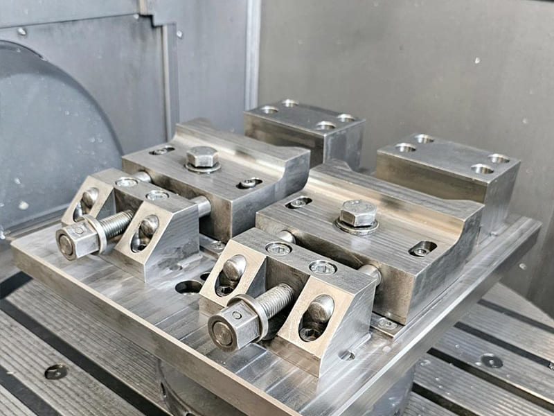
CNC işlemede, makine takımı övgünün çoğunu alır — ve parçalar doğru çıkmadığında suçlamanın çoğunu da. Ancak deneyimli tezgâh operatörleri, gerçek sorunların genellikle iş parçası bağlama sisteminde saklandığını bilir. Sub-mikron konumlandırma tekrarlanabilirliğine sahip bir 5-axis işleme merkezi, fikstür kesme kuvvetleri altında 0,05 mm hareket izin veriyorsa yine de tolerans dışı parçalar üretebilir. Bağlama aparatları ve fikstürler, CAD datum şeması ile fiziksel parça arasındaki bağlantıdır ve bu bağlantıyı yanlış kurmak pahalıya mal olur.
Bu makale, bağlama aparatları ve fikstürlerin üretim CNC ortamlarında gerçekte nasıl çalıştığı etrafında yapılandırılmıştır — ikisi arasındaki mühendislik ayrımları, operasyona göre fikstür tipleri, 3-2-1 konumlandırma prensibi dahil temel tasarım kuralları, malzeme seçimi, yaygın tasarım hataları ve fikstür stratejisinin üretim hacimlerine göre nasıl değiştiği ele alınmaktadır. Yeni bir parça ailesi için iş parçası bağlama sistemi belirliyorsanız veya bir tekrarlanabilirlik sorununu gideriyorsanız, bu üzerinde çalışmanız gereken çerçevedir.
Bağlama Aparatları ve Fikstürler Nedir? Gerçekten Önem Taşıyan Mühendislik Tanımları
Hem bağlama aparatları hem de fikstürler iş parçası bağlama cihazlarıdır, ancak farklı sorunları çözerler. Bunları birbirine karıştırmak yanlış spesifikasyon kararlarına yol açar.
CNC İşlemede Bağlama Aparatı Nedir?
Bir bağlama aparatı kesici takımı yönlendirir. Birincil işlevi takım yolu kontrolüdür — bir matkap, kılavuz veya raybanın iş parçasına nereden gireceğini yönlendiren fiziksel bir referans sağlar. Parça daha az rijit şekilde kısıtlanabilir, çünkü bağlama aparatının görevi takım hassasiyetidir, mutlak parça konumu değil.
Modern CNC atölyelerinde, bağlama aparatları bir zamanlar olduğundan daha dar bir role sahiptir. CNC makineleri takım yollarını G-kodu aracılığıyla tanımlar, bu nedenle takım yönlendirmesi büyük ölçüde program tarafından halledilir. Bağlama aparatları ikincil operasyonlar için hâlâ kullanışlıdır — zaten işlenmiş parçalara delik ekleme, yeniden işleme, onarım veya tam bir fikstür yapmanın gerekçelendirilmediği düşük hacimli işler. Ödünleşim operatör bağımlılığıdır: bağlama aparatına dayalı operasyonlar daha fazla manuel müdahale gerektirir ve fikstür tabanlı operasyonlara kıyasla döngüden döngüye daha fazla varyasyon üretir.
CNC İşlemede Fikstür Nedir?
Bir fikstür iş parçasını kontrol eder. Parçayı makine koordinat sistemine göre hassas şekilde konumlandırır, kesme kuvvetleri altında hareket etmesini önlemek için sıkıştırır ve bir partideki her döngüde tutarlı şekilde tutar. Fikstür, makinenin konumlandırma hassasiyetinin parçaya aktarılmasını sağlayan ikincil referans sistemidir.
Fikstürler, üretim CNC işlemesi için iş parçası bağlama çözümüdür. Operatör bağımlılığını azaltır, otomasyonu mümkün kılar ve süreç yeteneğini doğrudan kontrol eder. Yüksek hassasiyetli işlerde — havacılık braketleri, tıbbi implantlar, otomotiv güç aktarma organı bileşenleri — fikstür tasarımı parçanın kendisi kadar mühendislik ürünüdür.
| Özellik | Bağlama Aparatı | Fikstür |
|---|---|---|
| Birincil işlev | Kesici takımı yönlendirir | İş parçasını konumlandırır ve tutar |
| Operatör bağımlılığı | Daha yüksek — manuel kurulum içerir | Daha düşük — tekrarlanabilirlik için tasarlanmıştır |
| Hassasiyet mekanizması | Takım yolu kontrolü | İş parçası konum kontrolü |
| CNC uygulaması | İkincil veya düşük hacimli operasyonlar | Üretim, otomatik, yüksek hassasiyetli işler |
| Otomasyon uyumluluğu | Sınırlı | Otomatik hücrelerin temel bileşeni |
Bağlama Aparatları vs Fikstürler: Her Biri İşleme Hassasiyetini Nasıl Etkiler
Ayrım akademik değildir — ne tür bir hassasiyetin elde edilebileceğini ve bir parti boyunca sonuçların ne kadar tutarlı olduğunu doğrudan etkiler.
Takım Yönlendirmesi vs İş Parçası Kontrolü
Bir bağlama aparatı, takımın nereye gittiğini kontrol ederek hassasiyeti artırır. Bu, takımın fiziksel yolunun ana hata kaynağı olduğu durumlarda işe yarar — desteklenmeyen bir matkabın sapma eğiliminde olduğu manuel delme gibi. CNC'de makine zaten takım yolunu hassas şekilde kontrol eder. CNC'nin tek başına kontrol edemediği şey, parçanın nerede durduğudur. Fikstürlerin yaptığı da budur.
Pratik CNC operasyonlarında, fikstür tekrarlanabilirliği — parçanın döngüden döngüye aynı konumu ne kadar tutarlı şekilde işgal ettiği olarak tanımlanır — parti üretiminde boyutsal tutarlılığın birincil itici gücüdür. ±0,01 mm konumlandırma tekrarlanabilirliğine sahip bir fikstür, parçaların ±0,02 mm konumsal toleranslara güvenilir şekilde ulaşmasını sağlar. Tutarsız çene temasına sahip bir mengene, aynı CNC programlarıyla bile ±0,05–0,10 mm parçadan parçaya varyasyon verebilir.
Süreç Kararlılığı ve Operatör Bağımlılığı
Bağlama aparatına dayalı operasyonlar, operatörün her döngüde yüklemesini, hizalamasını ve doğrulamasını gerektirir. Varyasyon yükleme tekniği, sıkıştırma sırası ve dokunsal geri bildirim yoluyla girer. Düşük hacimli işler için — diyelim ki 5–20 parça — bu kabul edilebilir ve genellikle özel bir fikstür yapmaktan daha hızlıdır. 500+ parçalı partiler için bu varyasyon, çoğu kalite sisteminin kabul ettiğinin çok altında istatistiksel süreç yeteneğine (Cpk) birikir.
Fikstürler bunu azaltır. Bir fikstür doğrulandıktan sonra, parça konumu fikstür geometrisi tarafından belirlenir — operatörün bu belirli parçayı ne kadar dikkatli yüklediği tarafından değil. Fikstürleri ölçeklenebilir kılan ve hiç operatörün bulunmadığı otomatik hücrelerde vazgeçilmez kılan da budur.
CNC Fikstür Tipleri ve Her Birinin Ne Zaman Kullanılacağı
Farklı işleme operasyonları farklı fikstür mimarileri gerektirir. Doğru fikstür tipini seçmek, fikstürün boyutsal hassasiyeti kadar önemlidir.
Freze Fikstürleri
Freze fikstürleri, takım farklı özelliklere girdikçe kesme kuvvetlerinin yönünün değiştiği yüzey frezeleme, profil frezeleme ve çok yüzeyli operasyonlar sırasında parçaları sabitler. İyi freze fikstür tasarımı, sıklıkla yeterince ağırlık verilmeyen üç faktörü hesaba katar:
Titreşim kontrolü: Yüksek hızlı frezeleme dinamik kesme kuvvetleri üretir. Fikstürler, özellikle uzun erişimli operasyonlarda veya ince cidarlı özellikler işlenirken tırlama önlemek için yeterli sönümleme sağlamalıdır. Alüminyum iş parçaları için alüminyum 6061 fikstürler genellikle yeterlidir; ağır kesme altındaki çelik iş parçaları için çelik fikstür gövdeleri daha iyi dinamik sertlik sağlar.
Çok eksenli takım erişimi: 4 eksenli ve 5-axis frezelemede, fikstür, iş milinin özelliklere çarpışma olmadan birden fazla açıdan yaklaşmasına izin vermelidir. Fikstür geometrisi — özellikle kelepçe yüksekliği ve destek direği yerleşimi — fikstür imalatından önce CAM simülasyonunda doğrulanmalıdır.
Yüzey konum doğruluğu: Frezelenmiş özellikler arasında dar konum toleranslarına sahip parçalar için, datum yüzeylerindeki fikstür konumlandırma doğruluğu, konum toleransından en az 3–5 kat daha sıkı olmalıdır. ±0,05 mm özellik konumu gerektiren bir parça, ±0,010–0,015 mm'de fikstür konumlandırma doğruluğuna ihtiyaç duyar.
Tornalama ve Torna Fikstürleri
Tornalama fikstürleri, frezeleme fikstürlerinden farklı bir sorunu ele alır: parçanın dönme ekseni ile takım tezgahı iş mili merkez çizgisi arasındaki eş eksenliliği korumak. Bu iki eksen arasındaki herhangi bir sapma, eksantrik parçalar üretir — deliklere göre gerçek dönüş yapmayan dış çaplar veya eksene dik olmayan yüzeyler.
Standart üç ayaklı aynalar, genel tornalamada yuvarlak çubuk stok için yeterlidir. Aşağıdaki durumlarda yeterli değildir: parça silindirik değilse, datum belirli bir eksene sahip önceden işlenmiş bir özellikse, parça asimetrikse (hızda denge ve titreşim sorunları yaratır) veya salgı gereksinimleri ~0,02 mm'nin altındaysa.
Bu durumlar için özel torna fikstürleri, özel konumlandırma delikleri, hassas taşlanmış temas yüzeyleri ve dengeli kütle dağılımı kullanır. Salgı spesifikasyonlarının 0,005–0,010 mm olduğu pompa milleri veya iş mili bileşenleri gibi parçaların yüksek hızlı tornalanması için, kadranlı gösterge ayarlı dört ayaklı aynalar veya hassas pens fikstürleri standart uygulamadır.
Drilling and Tapping Fixtures
Drilling fixtures are most valuable in batch production where hole position consistency is required across many parts, or where hole patterns relative to previously machined features must be held to positional tolerances that manual setup can’t reliably achieve.
Key design consideration: bush diameter tolerance versus drill diameter creates the actual positional error. A drill bush with +0.02 mm bore tolerance on a drill with −0.01 mm diameter tolerance allows 0.015 mm of theoretical movement before any part positioning error is added. For holes requiring ±0.1 mm positional tolerance, this is adequate. For ±0.03 mm, it’s not — and ground bushes with tighter tolerances are required.
Integration with CNC machining centers has largely replaced standalone drilling fixtures for primary operations. Drilling jigs remain in use for secondary operations, rework, and production environments where dedicated drilling machines (rather than machining centers) handle high-volume hole patterns.
Modular Fixtures
Modular fixture systems — T-slot plates, precision hole grids, and standardized locating elements — offer reusability across different parts by combining standard components into job-specific configurations. The primary advantage is cost and lead time: a modular setup can be assembled in hours using components already on the shelf, compared to weeks for a dedicated machined fixture.
The performance trade-off is locating accuracy. Modular systems typically achieve ±0.02–0.05 mm repeatability depending on the system quality and how carefully the setup is assembled. Dedicated machined fixtures can achieve ±0.005–0.015 mm. For prototype work, short-run production, and parts with tolerances in the ±0.05 mm range, modular fixtures are often the right economic decision. For high-precision production work, they’re a compromise.
Where Jigs Still Add Value in CNC Workshops
Jigs haven’t disappeared — their role has simply shifted toward applications where fixture investment isn’t justified.
Drill Jigs for Secondary Operations
After a part completes its main CNC operation, secondary features sometimes need to be added: cross-holes that couldn’t be accessed in the original setup, tapped holes in a face that was used as a fixture datum, or features added during engineering change orders after the production fixture was already built.
Drill jigs handle these situations efficiently. A simple plate jig with correctly positioned bushes and locating pins can add features within ±0.15–0.20 mm positional accuracy — adequate for most non-critical secondary features — without the cost and lead time of a new fixture. The operator loads the part, clamps it against the jig, and drills. For 10–50 parts, this is faster than modifying the production fixture.
Indexing and Template Jigs
Indexing jigs enable evenly spaced hole patterns — bolt circles, equally distributed features — without requiring complex CNC programming for every feature. The jig rotates the part to each angular position while a fixed drill or tap performs the operation.
This approach makes most sense on manual machines or simple CNC setups where adding a rotation axis in the program would require workholding changes or more complex G-code. On a 5-axis machining center, indexing jigs are rarely justified. On a 2-axis CNC drilling machine, they add significant capability at low cost.
Core Design Rules: What Separates Effective Fixtures from Expensive Problems
Most fixture failures aren’t caused by poor materials or bad machining. They come from incorrect application of locating and clamping principles at the design stage.
The 3-2-1 Locating Principle
Every rigid body in space has six degrees of freedom (DOF): three translational (X, Y, Z) and three rotational (rotation about X, Y, Z). A fixture must constrain all six to define part position deterministically. The 3-2-1 method is the standard engineering approach:
- 3 locating points on the primary datum surface: constrain Z-translation and two rotations (the largest, flattest surface typically)
- 2 locating points on the secondary datum surface: constrain Y-translation and one rotation
- 1 locating point on the tertiary datum surface: constrain X-translation
This provides exactly-constrained positioning with no redundancy. Adding a fourth locator to a primary plane creates over-constrained geometry — the part rocks between the four locators depending on which three make contact, producing position variation that no amount of clamping force eliminates. This is a very common fixture design error that shows up as inconsistent first-article results.
Aligning fixture datums with the CAD datum scheme is not optional. If the print calls out datum A as the bottom face, datum B as a side face, and datum C as an end face — those are the surfaces that must define fixture position. Using a different face as a locating reference, even one that’s more convenient, introduces datum shift errors that directly translate into positional deviations on the part.
Clamping Strategy: Less Force, Better Placement
A frequent fixture design misconception is that more clamping force equals more stability. In reality, over-clamping causes deformation — particularly in aluminum components, thin-wall features, and long profiles.
Consider a 300 mm × 80 mm × 15 mm aluminum 6061 bracket machined in a vice. Applying 2,000 N clamping force on an unsupported section of the wall elastically deflects the workpiece by a measurable amount during machining. The part springs back when unclamped, and the machined dimensions are shifted. The machine did exactly what the program said; the workpiece moved.
Effective clamping follows three rules:
- Clamp toward locators, not across unsupported spans
- Apply clamps at locations where the workpiece is structurally supported beneath
- Use the minimum clamping force that prevents movement under peak cutting forces — typically calculated from the cutting force model, not from “tight as possible”
For thin-wall aluminum aerospace parts, clamping forces are often calculated explicitly and applied with torque-controlled hydraulic clamps to ensure consistency across operators and shifts.
Rigidity, Tool Clearance, and Chip Evacuation
Fixture rigidity must resist the dynamic cutting forces without deflection — but the fixture also must not block the tool. These two requirements pull in opposite directions and must be resolved in CAM simulation before the fixture is manufactured.
In 5-axis machining, the spindle tilts to various angles to access compound surfaces. Support pillars, clamp bodies, and fixture walls must all clear the tool assembly (holder + tool) at every programmed orientation. A collision in simulation costs nothing to fix. The same collision discovered on the machine damages the fixture, the part, and potentially the spindle — at considerable cost.
Chip evacuation is the other frequently overlooked factor. Pockets in fixtures that collect chips create recutting, elevated surface temperatures, and accelerated tool wear. Well-designed fixtures have slots, holes, or angled faces that allow chips to fall clear of the cutting zone. For aluminum machining with flood coolant, this is less critical; for dry machining of steel, chip management can meaningfully affect surface finish and tool life.
Materials and Manufacturing for CNC Jigs and Fixtures
Material selection for fixtures is a practical engineering decision governed by production volume, required accuracy, and machining speed.
Takım Çeliği
Tool steel (P20, H13, or D2 depending on application) is specified for fixtures that will see high production volumes, heavy cutting forces, or repeated loading that would wear softer materials. Hardened tool steel fixtures maintain locating surface dimensions over tens of thousands of cycles — critical when locating pin bores and datum pads must remain within ±0.005 mm over a production run.
The cost premium is significant: machining hardened steel takes longer, requires harder tooling, and often involves grinding operations to achieve the surface finish and flatness needed at locating features. For high-volume production where fixture life and dimensional stability justify the investment, it’s the correct specification.
Aluminum (6061-T6 or 7075-T6)
Aluminum fixtures dominate CNC production environments for good reason. 6061-T6 provides adequate stiffness for most milling and turning fixture applications, machines quickly, and produces excellent surface finish. A fixture that takes 8 hours to machine in 4140 steel takes 2–3 hours in 6061, with equivalent dimensional accuracy in the as-machined condition.
For fixtures handling harder workpieces or heavier cuts, 7075-T6 provides higher yield strength (~503 MPa vs ~276 MPa for 6061) with similar machinability. Insert pockets at locating points — hardened steel inserts pressed into aluminum fixture bodies — protect the locating surfaces from wear without the cost and lead time of all-steel construction.
Engineering Plastics (POM, Nylon, UHMW-PE)
Plastic elements in fixtures serve specific purposes rather than structural roles. POM (Delrin) and UHMW-PE contact pads prevent marring of finished or cosmetic surfaces. Nylon locating blocks provide electrical isolation when required. Soft jaws made from Delrin or aluminum allow light clamping on finished surfaces without damage.
These materials are not substitutes for metal fixture bodies in load-bearing applications. Their lower modulus (POM ~3 GPa vs aluminum ~69 GPa) means they deform under typical cutting forces in ways that metal doesn’t.
Üretim Yöntemleri
CNC işleme is the standard for production fixtures. Dimensional accuracy of ±0.005–0.010 mm is routinely achievable on locating features, and the process integrates directly with CAD/CAM fixture design workflows.
3D baskı (FDM or SLA) serves a legitimate but limited role: design verification, checking fit before cutting metal, and temporary fixtures for very light operations or ergonomic positioning aids. Printed fixtures typically don’t have sufficient stiffness or wear resistance for production CNC operations — but as a design validation tool before committing to metal, they save real time and cost.
Fixture Strategy Across Production Volumes
Fixture design decisions don’t exist in isolation from production context. The right workholding for 10 parts is rarely right for 10,000.
Prototype and Low-Volume (1–50 Parts)
Speed and flexibility matter more than optimization at this stage. Soft jaws, modular fixtures, and standard vises handle most prototype machining adequately. The priority is turning around parts quickly for validation — not minimizing cycle time or achieving process capability targets that apply to production.
Acceptable approach: modular fixture or soft jaws in a milling vise, manual datum setup with indicator verification, operator-adjusted clamping. Locating repeatability of ±0.05 mm is usually fine when each part is verified by CMM after machining.
Medium to High Volume (500–50,000 Parts)
Dedicated fixtures become economically justified as volume increases. The fixture’s cost amortizes over part count — a $3,000 fixture on a 5,000-part run adds $0.60/part while potentially saving 2–3 minutes of setup time per part (significant at scale) and improving Cpk from borderline to production-acceptable.
At this volume, fixture design should target locating repeatability of ±0.010–0.020 mm, with validated clamping sequences and standardized torque specifications. Process capability studies on the first production run establish whether the fixture-plus-machine system achieves the required Cpk, typically ≥1.33 for production release.
Automated and Robotic CNC Cells
In lights-out machining cells, fixtures are active system components, not passive holders. They require:
Zero-point clamping systems: Standardized mounting that allows pallets to be exchanged by robot or pallet changer with repeat positioning accuracy of ±0.003–0.005 mm — without manual locating verification.
Part presence and clamping confirmation sensors: Inductive or pneumatic sensors integrated into the fixture that confirm the part is seated correctly and clamps have engaged before the cycle starts. A missing part or improperly seated workpiece that passes undetected into a cutting cycle causes collisions and scrap.
Probing compatibility: Many automated cells use on-machine probing to verify workpiece position before cutting, compensating for minor fixture variations. Fixtures must allow probe access to reference features without collision.
Common Fixture Design Mistakes and How to Avoid Them
The following three mistakes account for the majority of fixture-related quality problems in CNC production:
Over-clamping on thin or compliant sections: The part deforms during machining, springs back after unclamping, and dimensions shift. The machine performed correctly; the workpiece didn’t. Fix: calculate the required clamp force from cutting force data, position clamps at structurally supported locations, and support thin sections from beneath rather than clamping across them.
Ignoring thermal expansion and residual stress: Long cycle times on large parts generate heat. A constrained aluminum workpiece expanding 0.05 mm during a 2-hour milling cycle accumulates stress that releases as geometric distortion when the clamps are removed. Fix: allow controlled thermal freedom in long-axis directions, sequence rough and finish operations with soak time between them, and consider fixture material CTE compatibility with workpiece material.
Designing fixtures without simultaneously designing tool paths: Clamp bodies that block 5-axis spindle approach angles, support pillars that trap chips, or fixture walls that prevent probe access — these only emerge in CAM simulation. Fix: fixture design and CAM programming must proceed in parallel, with collision verification as a required step before fixture manufacture.
Sonuç
CNC machining performance is a product of three things working together: machine capability, cutting strategy, and workholding. Of these, workholding — specifically jigs and fixtures — is the variable most directly under the engineer’s control and the one most often underspecified. A correctly designed fixture converts the machine’s positioning repeatability into actual part accuracy. A poorly designed one introduces variation that no amount of machine calibration or programming skill can compensate for.
Jigs retain value for secondary operations, rework, and low-volume flexible setups. Fixtures govern everything else in production CNC: milling, turning, drilling, and automated cell operation. Getting fixture design right — applying 3-2-1 locating correctly, controlling clamping force to prevent deformation, ensuring tool and chip clearance, selecting material appropriate to production volume — is what separates shops that consistently hit tolerance from those that constantly troubleshoot.
Sıkça Sorulan Sorular
Are jigs still used in CNC machining?
Yes, in specific situations. Jigs are most useful for secondary operations after main machining — adding holes to completed parts, rework, or quick-turn low-volume jobs where building a dedicated fixture isn’t cost-justified. For primary CNC operations requiring repeatability and automation, fixtures have largely replaced jigs.
What’s the difference between a CNC fixture and a vise?
A vise is a general-purpose workholding tool optimized for flexibility and fast setup. A CNC fixture is purpose-designed to locate a specific part at a specific datum position, repeatably, cycle after cycle. Vises rely on operator skill for consistent positioning; fixtures embed that positioning into their geometry. The accuracy difference — ±0.05–0.10 mm for a vise vs ±0.005–0.020 mm for a precision fixture — matters significantly in tight-tolerance production work.
How do I design a custom fixture for CNC milling?
Start with the part’s datum scheme from the engineering drawing. Apply the 3-2-1 locating principle to constrain all six degrees of freedom from those datums. Design clamping to act toward locators at structurally supported locations. Verify tool clearance and chip evacuation in CAM simulation before manufacturing the fixture. Validate locating repeatability with a CMM before production release.
What materials work best for long-term CNC fixtures?
Tool steel (P20 or hardened D2) for high-volume production where wear resistance and long-term dimensional stability are critical. Aluminum 6061-T6 or 7075-T6 for medium-volume work where machining speed and cost efficiency are priorities — use hardened inserts at locating points to manage wear. Engineering plastics for contact surfaces where part protection is required.
Can fixtures improve CNC tolerance consistency?
Absolutely — and it’s one of the most cost-effective improvements available in a CNC process. Fixture-driven repeatability directly affects Cpk. Improving locating repeatability from ±0.05 mm to ±0.010 mm on a feature with a ±0.05 mm tolerance shifts Cpk from approximately 0.67 to well above 1.33 — the difference between a process that produces scrap and one that runs in production.


