
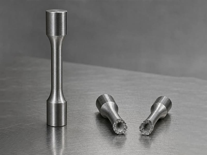
A resistência à tração é uma das propriedades mecânicas mais fundamentais usadas para descrever como um material se comporta sob forças de tração ou estiramento. Ela define a tensão máxima que um material pode suportar antes da falha e desempenha um papel crítico na seleção de materiais, no projeto estrutural e na avaliação de segurança em aplicações de engenharia.
Este artigo explica o que é resistência à tração, como ela é medida por meio de ensaios padronizados e como ela aparece em uma curva tensão–deformação. Também esclarece o significado de engenharia da resistência à tração e por que ela é importante ao projetar componentes que devem suportar cargas de forma confiável sem se romper.
O Que É Resistência à Tração?
Resistência à tração é formalmente definida como a tensão de engenharia máxima que um material pode suportar sob carregamento de tração uniaxial antes da fratura. Ela é calculada dividindo a maior força de tração registrada pela área da seção transversal original do corpo de prova durante um ensaio de tração. Esse valor é comumente referido como Resistência à Tração Final (UTS).
Do ponto de vista da engenharia, a UTS representa um limite de falha, não um limite operacional utilizável. Ela marca o ponto em que um material não consegue mais sustentar o aumento de carga e começa a fraturar, frequentemente após deformação plástica significativa em materiais dúcteis. Para materiais frágeis, essa tensão máxima pode ocorrer com pouco aviso e alongamento mínimo, tornando sua interpretação ainda mais crítica.
Um equívoco frequente é equiparar tensão máxima com tensão segura. Em componentes reais, os engenheiros projetam bem abaixo da resistência à tração aplicando fatores de segurança que consideram a variabilidade nas propriedades dos materiais, defeitos de fabricação, incerteza de carregamento e condições de serviço. Usar a UTS diretamente para projeto ignoraria essas realidades e aumentaria significativamente o risco de falha.
Na prática, a resistência à tração serve como uma propriedade comparativa e de triagem. Ela ajuda os engenheiros a diferenciar classes de materiais, avaliar os efeitos do tratamento térmico e estimar a resistência à fratura catastrófica. No entanto, ela deve sempre ser interpretada em conjunto com o limite de escoamento, a ductilidade e o modo de carregamento para ter valor real de engenharia.
Como a Resistência à Tração É Medida e Calculada?
A resistência à tração é obtida por meio de um ensaio de tração uniaxial padronizado, projetado para carregar um material em tração controlada até a falha. Embora a configuração do ensaio pareça simples, a forma como a tensão é definida e calculada carrega implicações importantes de engenharia.
O Ensaio de Tração: O Que Realmente Acontece
Um corpo de prova padronizado é fixado em ambas as extremidades e tracionado a uma taxa controlada usando uma máquina de ensaio universal. À medida que a força aplicada aumenta, a máquina registra continuamente carga e alongamento. O ensaio prossegue através de deformação elástica, escoamento (para materiais dúcteis), deformação plástica, estricção e, finalmente, fratura. A carga máxima atingida antes da fratura é o valor-chave usado para determinar a resistência à tração.
Tensão = Força / Área: Uma Interpretação de Engenharia
A resistência à tração é calculada usando a definição de tensão de engenharia:
-
Tensão = Força aplicada ÷ área da seção transversal original
Do ponto de vista da engenharia, essa definição é intencional. Usar a área original—em vez da área que encolhe continuamente durante a estricção—fornece uma base consistente para comparação entre materiais, tratamentos térmicos e normas. Isso permite que os projetistas comparem valores de resistência à tração entre folhas de dados sem precisar de dados completos de deformação.
Área Original vs. Área em Tempo Real
Durante a deformação plástica, especialmente próxima à fratura, a seção transversal do corpo de prova pode reduzir significativamente. Se a tensão fosse calculada usando a área instantânea, o valor resultante seria muito maior e é referido como tensão verdadeira, não resistência à tração de engenharia. Embora a tensão verdadeira seja valiosa em modelagem avançada de materiais, a UTS é sempre baseada na área original para relatórios padrão e referência de projeto.
Unidades: MPa vs. psi
A resistência à tração é tipicamente reportada em:
-
MPa (megapascais) em normas métricas e baseadas em ISO
-
psi (libras por polegada quadrada) em normas imperiais ou dos EUA
1 MPa equivale a 1 N/mm², tornando-o diretamente compatível com desenhos de engenharia comuns e modelos de elementos finitos. A escolha da unidade não altera o comportamento do material, mas a clareza é essencial ao comparar especificações entre regiões.
Exemplo Prático
Se um corpo de prova atinge uma carga de pico de 50 kN e tem uma área de seção transversal original de 100 mm², a resistência à tração é de 500 MPa—independentemente de quanto estriccionamento ocorra depois.
A engenharia é um ponto de partida: o cálculo da resistência à tração prioriza comparabilidade e padronização, não a tensão local em tempo real. Compreender essa distinção evita interpretações errôneas e uso indevido em decisões de projeto.
O que Acontece Durante um Ensaio de Tração? Compreendendo a Curva Tensão–Deformação
Um ensaio de tração é melhor compreendido pela leitura da curva tensão–deformação, que mapeia como um material responde ao aumento da carga de tração. Cada segmento da curva corresponde a um mecanismo de deformação distinto com significado claro para a engenharia.
Região Elástica: Deformação Reversível
No início do ensaio, a tensão e a deformação aumentam proporcionalmente. Esta região elástica é regida pelo módulo de Young, e a deformação é totalmente reversível. Se a carga for removida aqui, o material retorna às suas dimensões originais. Para os engenheiros, esta região define rigidez, não resistência, e é crítica para cálculos de deflexão e vibração.
Escoamento: Início da Mudança Permanente
No ponto de escoamento, o material transita do comportamento elástico para o plástico. Além deste ponto, a deformação torna-se permanente. Alguns materiais exibem um ponto de escoamento claro; outros mostram escoamento gradual. No projeto, a resistência ao escoamento—não a resistência à tração—frequentemente define a tensão máxima admissível para componentes estruturais.
Deformação Plástica: Suporte de Carga com Mudança de Forma
Após o escoamento, o material sofre deformação plástica. A tensão continua a aumentar à medida que o material endurece por deformação, permitindo-lhe suportar cargas maiores apesar do alongamento permanente. Esta região reflete a ductilidade e capacidade de absorção de energia, do material, que são essenciais para componentes sujeitos a sobrecarga ou impacto.
Estriccionamento: Localização da Deformação
No pico da curva, o material atinge sua resistência máxima à tração. Além deste ponto, a deformação localiza-se numa região estreita conhecida como estriccionamento. Embora a capacidade de carga global diminua, a tensão real local continua a aumentar. Do ponto de vista da engenharia, o estriccionamento sinaliza o início da deformação instável e falha iminente.
Fratura: Falha Final
O ensaio conclui-se com fratura, que pode ser dúctil (com estriccionamento notável e aparência fibrosa) ou frágil (com deformação plástica mínima). As características da fratura fornecem informações valiosas sobre a qualidade do material, tratamento térmico e adequação para condições de carregamento específicas.
Perspetiva da Engenharia
A curva tensão–deformação mostra que a resistência à tração é apenas um ponto num mapa de comportamento muito mais rico. O limite elástico, o comportamento de escoamento, a deformação plástica e o modo de fratura, em conjunto, determinam como um material se comporta em componentes reais. Os engenheiros que compreendem a curva completa podem selecionar materiais e fatores de segurança que se alinham com as condições reais de serviço—em vez de confiar num único número de destaque.
Qual é a Diferença Entre Resistência à Tração e Resistência ao Escoamento?
Embora a resistência à tração e a resistência ao escoamento sejam frequentemente listadas juntas nas fichas técnicas dos materiais, elas desempenham papéis muito diferentes no projeto de engenharia. Confundir as duas é uma fonte comum de sobredimensionamento, deformação inesperada ou falha prematura.
Por que os Engenheiros se Concentram Mais na Resistência ao Escoamento
Limite de escoamento define o nível de tensão no qual um material começa a deformar-se plasticamente. Além deste ponto, o material não retornará à sua forma original após o descarregamento. Para a maioria dos componentes estruturais e mecânicos, a deformação permanente—não a fratura—é o modo de falha funcional. Eixos que se dobram, suportes que se deformam ou carcaças que perdem alinhamento são frequentemente inaceitáveis muito antes de a peça realmente quebrar.
Como resultado, a tensão admissível de projeto é tipicamente derivada da resistência ao escoamento dividida por um fator de segurança, not from tensile strength.
Where Tensile Strength Still Matters
Tensile strength (UTS) represents the maximum stress a material can withstand before fracture. It remains important in:
-
Brittle materials, where yielding is minimal and fracture occurs near UTS
-
Failure analysis, to understand ultimate load capacity
-
Comparative material screening, especially across heat treatments or alloy families
-
Applications involving overload or crash scenarios, where fracture resistance matters
Ductile vs. Brittle Materials: Different Emphasis
Material behavior strongly influences which property dominates design decisions.
| Aspeto | Resistência ao escoamento | Resistência à tração |
| What it indicates | Onset of permanent deformation | Maximum stress before fracture |
| Design relevance | Primary limit for most components | Secondary or conditional limit |
| Ductile materials | Clearly defined, critical | Occurs well after yielding |
| Brittle materials | May be undefined or close to UTS | Often the controlling property |
Em ductile materials (e.g., most steels, aluminum alloys), yield strength is the controlling parameter. In brittle materials (e.g., cast iron, ceramics), tensile strength becomes more relevant because failure occurs with little plastic deformation.
Conclusões da engenharia
The key distinction is this:
-
Yield strength protects function and geometry
-
Tensile strength defines catastrophic failure
Good engineering practice recognizes that tensile strength alone does not ensure safe or reliable design. Understanding how yield and tensile strength interact—within the context of material ductility and service conditions—is essential for responsible material selection and structural integrity.
How Does Tensile Strength Differ from Other Mechanical Properties?
Tensile strength is only one dimension of a material’s mechanical behavior. In engineering practice, it must be interpreted alongside stiffness and strength under different loading modes. Many design errors stem from assuming these properties are interchangeable.
Key Mechanical Properties Compared (Engineering View)
| Propriedade | O Que Ela Descreve | What It Controls in Design | Common Misunderstanding |
| Resistência à Tração (UTS) | Maximum stress before fracture in tension | Ultimate failure limit | “Higher UTS means a stiffer or safer part” |
| Young’s Modulus | Slope of elastic stress–strain curve | Stiffness, deflection, vibration | Confused with strength |
| Resistência à compressão | Resistance to crushing loads | Load capacity in compression | Assumed equal to tensile strength |
| Resistência ao cisalhamento | Resistance to sliding failure | Pins, bolts, joints | Approximated from tensile strength |
Tensile Strength vs. Young’s Modulus
Young’s modulus measures stiffness—how much a material stretches elastically under load—not how much load it can carry before failure. Two materials can have similar tensile strength but vastly different stiffness. Increasing tensile strength does não reduce deflection; only modulus does.
Tensile vs. Compressive Strength
Many materials behave differently in tension and compression. Metals often have similar values, but brittle materials (cast iron, ceramics, concrete) are far stronger in compression than in tension. Designing compression-loaded parts using tensile strength alone can be dangerously misleading.
Tensile vs. Shear Strength
Resistência ao cisalhamento governs failure in joints, fasteners, and thin sections. While often estimated as a fraction of tensile strength, the actual value depends on microstructure, heat treatment, and loading direction. Direct shear data is preferred when joints are critical.
Conclusões da engenharia
Tensile strength answers a narrow question: how much tensile stress causes fracture? It does não describe stiffness, deflection, compressive behavior, or joint performance. Robust engineering decisions emerge only when tensile strength is evaluated in context, alongside modulus and strength in the relevant loading mode.
What Factors Affect the Tensile Strength of Materials?
Tensile strength is not an intrinsic constant of a material family. It emerges from composition, microstructure, processing history, and service conditions. Understanding porquê tensile strength changes is essential for both material selection and manufacturing control.
Key Factors → Mechanisms → Strength Response
-
Material Composition and Alloying Alloying elements strengthen materials by solid-solution strengthening, precipitation, or phase transformation. For example, adding carbon to steel or zinc to aluminum alloys increases resistance to dislocation motion, raising tensile strength. However, higher alloy content can also reduce ductility and machinability—an important trade-off in manufacturing.
-
Grain Size and Microstructure Finer grains generally increase tensile strength through the Hall–Petch effect, which limits dislocation movement at grain boundaries. Microstructural phases (e.g., ferrite vs martensite in steel) strongly influence strength levels. Two materials with identical composition can show very different tensile strength due to microstructural differences alone.
-
Processing History: Cold Work and Heat Treatment
-
Cold working increases tensile strength by strain hardening but reduces ductility.
-
Tratamento térmico can either increase strength (quenching and aging) or reduce it (annealing) by modifying phase structure and relieving internal stresses. Manufacturing history is therefore inseparable from tensile strength values on datasheets.
-
-
Temperature and Strain Rate Tensile strength generally decreases with increasing temperature due to enhanced atomic mobility. Conversely, higher strain rates often increase apparent strength, especially in metals and polymers. This explains why room-temperature test data may not represent high-temperature or impact loading conditions.
-
Defects, Porosity, and Impurities Voids, inclusions, and microcracks act as stress concentrators, reducing effective load-bearing area and lowering tensile strength. In cast or additively manufactured parts, defect population often dominates strength more than nominal alloy properties.
Conclusões da engenharia
Tensile strength reflects a system of material + process + environment, not just chemistry. For engineers, this means strength values are only meaningful when linked to processing route and service conditions. For buyers, it explains why parts made from the “same material” can show different performance—and why supplier process control directly affects mechanical reliability.
How Does Tensile Strength Vary Across Different Materials?
Tensile strength varies widely across material classes because the mechanisms that resist tensile loading are fundamentally different. Comparing numbers without understanding these mechanisms often leads to poor material choices.
Tensile Strength Across Major Material Types
| Tipo de material | Typical Tensile Strength Range | Características principais | Implicações de engenharia |
| Metals (steel, aluminum, copper alloys) | ~100–2000 MPa | Ductile (most), isotropic, heat-treatable | Strength must be balanced with yield, fatigue, and machinability |
| Plastics / Engineering Polymers | ~20–150 MPa | Low modulus, viscoelastic, temperature-sensitive | High tensile strength does not imply stiffness or load capacity |
| Composites (e.g., CFRP, GFRP) | ~300–3000+ MPa (directional) | Anisotropic, fiber-dominated behavior | Strength depends on fiber direction and layup, not bulk material |
Metals: Strength with Predictable Behavior
Em metais, tensile strength reflects resistance to dislocation motion within a crystalline lattice. Steels span the widest range—from low-carbon structural steels to ultra-high-strength alloy steels—while aluminum and copper alloys offer lower strength but better corrosion resistance or conductivity. Crucially, metals usually exhibit clear yield behavior, allowing engineers to design conservatively using yield strength rather than UTS.
Plastics: Tensile Strength Without Stiffness
Plastics and engineering polymers often show modest tensile strength compared to metals, but their more critical limitation is low stiffness (Young’s modulus). A polymer with 80 MPa tensile strength may still deform excessively under load. Additionally, tensile strength in plastics is highly sensitive to temperature, strain rate, and time (creep), making room-temperature datasheet values an incomplete basis for design.
Composites: Very High but Directional Strength
Fiber-reinforced composites can achieve extremely high tensile strength along the fiber direction, often exceeding metals on a strength-to-weight basis. However, this strength is anisotropic. Off-axis loading, poor fiber alignment, or weak interlaminar bonding can drastically reduce effective tensile performance. Here, “tensile strength” is inseparable from layup design.
Why Tensile Strength Alone Is Not Enough
Across all material classes, tensile strength answers only one question: how much tensile stress causes fracture under ideal test conditions? It does not describe stiffness, ductility, fatigue life, impact resistance, or behavior under real service environments.
A engenharia é um ponto de partida: Tensile strength is useful for screening and comparison within a material class, but it cannot be used in isolation to select materials across metals, plastics, and composites. Robust material selection integrates tensile strength with modulus, yield behavior, environmental sensitivity, and manufacturing constraints.
Why Tensile Strength Matters in Engineering Design and Manufacturing
Na prática da engenharia, tensile strength matters because it anchors design decisions to a measurable failure limit. While it is not always the controlling parameter, it frames how engineers think about safety, risk, and material capability throughout the product lifecycle.
Safety Factors and Structural Design
Tensile strength provides the upper bound against which safety factors are applied. Designers rarely allow stresses to approach UTS; instead, it informs how conservative a design must be relative to yield strength, fatigue limits, and service loads. Materials with higher tensile strength often allow thinner sections or lower mass, but only when stiffness, buckling, and fatigue are also satisfied.
Role in Failure Analysis
In failure investigations, tensile strength helps distinguish overload failures from those caused by fatigue, corrosion, or defects. If fracture stresses approach UTS, overload is likely; if failure occurs well below UTS, attention shifts to stress concentrations, surface quality, or microstructural issues. Here, tensile strength is a diagnostic reference, not the root cause.
Practical Impact on CNC Machined Parts
Para usinagem CNC, tensile strength influences material choice and process planning. Higher-strength alloys can improve load capacity but often increase tool wear, cutting forces, and cycle time. Conversely, selecting a material with “excess” tensile strength can raise cost without improving part performance. Effective material selection balances tensile strength with machinability, yield behavior, and tolerance requirements.
When Tensile Strength Is Not the Key Metric
There are many cases where tensile strength is secondary:
-
Deflection-limited designs → stiffness (Young’s modulus) dominates
-
Fatigue-loaded components → endurance limit or fatigue strength controls
-
Compression- or shear-dominated parts → compressive or shear strength matters more
-
Montagens de precisão → yield strength and dimensional stability are critical
Conclusões da engenharia
Tensile strength matters most as a boundary condition—it defines what failure looks like, not how a part should normally operate. In sound engineering design and manufacturing, tensile strength is used in context: combined with safety factors, failure modes, and process realities to deliver reliable, cost-effective components rather than chasing the highest possible strength number.
What Are the Limitations of Tensile Strength as a Design Parameter?
Although tensile strength is widely used, it is a limited and sometimes misleading design parameter when taken in isolation. Many engineering failures occur well below a material’s ultimate tensile strength, highlighting the need for a broader performance view.
The Risk of a Single-Number Mindset
Tensile strength describes behavior under monotonic, uniaxial tension in a controlled test. Real components rarely experience such idealized loading. Stress concentrations, multiaxial loads, surface finish, and manufacturing defects can all trigger failure long before UTS is reached. Designing purely “to tensile strength” often leads to false confidence or unnecessary overdesign.
Disconnect from Fatigue, Impact, and Creep
-
Fadiga: Components under cyclic loading usually fail at stress levels far below tensile strength. Fatigue strength or endurance limit—not UTS—governs life expectancy.
-
Impact loading: Materials with high tensile strength can still perform poorly under sudden loads if impact toughness is low. Brittle fracture is a classic example.
-
Fluência: At elevated temperatures, materials may deform gradually under constant load. Tensile strength measured at room temperature provides little insight into long-term creep behavior.
Implications for Engineering Design
Because tensile strength does not capture time-dependent or energy-based failure modes, it must be evaluated alongside other properties:
-
Yield strength for permanent deformation control
-
Fatigue strength for cyclic durability
-
Impact resistance for shock or crash scenarios
-
Creep resistance for high-temperature service
Conclusões da engenharia
Tensile strength is best viewed as a boundary indicator, not a comprehensive measure of material performance. Robust engineering design relies on integrated property assessment, ensuring that strength, durability, and reliability align with real service conditions rather than a single headline value.
Resumo
Tensile strength is a foundational mechanical property, but it is not a universal measure of material performance. It defines the maximum tensile stress a material can withstand before fracture, providing an important reference point for comparing materials and understanding ultimate failure limits.
Na prática da engenharia, how tensile strength is interpreted matters more than how high the number is. Designing directly to tensile strength ignores permanent deformation, fatigue damage, impact behavior, and environmental effects that often govern real-world failures. Yield strength, ductility, and fatigue resistance usually play a more direct role in ensuring functional reliability and dimensional stability.
Robust engineering decisions treat tensile strength as part of a broader performance framework. When combined with yield behavior, fatigue life, loading conditions, and manufacturing constraints, tensile strength becomes a useful boundary indicator rather than a misleading target. Understanding this context allows engineers, designers, and buyers to select materials that deliver reliable performance—not just impressive datasheet values.
Perguntas frequentes
Is higher tensile strength always better?
Not necessarily. Higher tensile strength increases the margin before fracture, but it often comes with trade-offs such as reduced ductility, tougher machining, and higher cost. Many components are yield-, fatigue-, or stiffness-limited, meaning they fail or deform permanently long before reaching tensile strength. Selecting a material solely for high UTS can lead to overdesign without improving real performance.
Why do some materials with high tensile strength fail easily?
Failure can occur far below UTS due to stress concentrations, fatigue loading, impact, corrosion, or manufacturing defects. Materials with high tensile strength but low toughness may fracture suddenly under shock or crack growth. In service, loading mode and environment usually dominate over the headline tensile number.
How does tensile strength affect CNC machined parts?
Tensile strength influences material selection and process planning. Higher-strength alloys typically require lower cutting speeds, more rigid setups, and wear-resistant tooling, which increases cycle time and cost. For many CNC parts, selecting a material with adequate (not maximum) tensile strength improves machinability, surface finish, and dimensional control while still meeting functional loads.
Can tensile strength be improved by heat treatment?
Yes, for many metals. Quenching and tempering, solution treating and aging, or work hardening can significantly increase tensile strength by altering microstructure. However, strengthening treatments often reduce ductility and can increase distortion or residual stress—factors that must be managed during machining and assembly.
What tensile strength values are typical for common metals?
Typical ranges (approximate, condition-dependent) include:
-
Low-carbon steel: ~350–550 MPa
-
Alloy/heat-treated steel: ~700–1500+ MPa
-
Aluminum alloys: ~150–600 MPa
-
Copper alloys (brass/bronze): ~200–600 MPa
-
Titanium alloys: ~800–1100 MPa


