
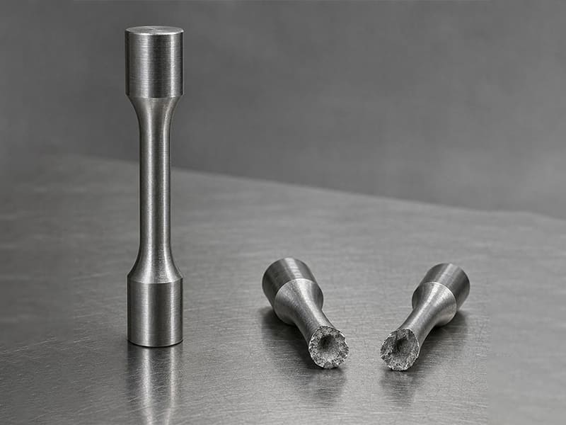
Предел прочности при растяжении — одно из наиболее фундаментальных механических свойств, используемых для описания поведения материала под действием растягивающих или удлиняющих усилий. Он определяет максимальное напряжение, которое материал может выдержать до разрушения, и играет критическую роль при выборе материалов, проектировании конструкций и оценке безопасности в инженерных приложениях.
В этой статье объясняется, что такое предел прочности при растяжении, как он измеряется с помощью стандартизированных испытаний и как он отображается на кривой напряжение–деформация. Также разъясняется инженерный смысл предела прочности при растяжении и почему он важен при проектировании компонентов, которые должны надёжно выдерживать нагрузки без разрушения.
Что такое предел прочности при растяжении?
Прочность на разрыв формально определяется как максимальное инженерное напряжение, которое материал может выдержать при одноосном растяжении до разрушения. Он рассчитывается путём деления наибольшей зафиксированной растягивающей силы на исходную площадь поперечного сечения образца в ходе испытания на растяжение. Это значение обычно называют пределом прочности при растяжении (UTS).
С инженерной точки зрения UTS представляет собой порог разрушения, а не рабочий предел. Он обозначает точку, в которой материал больше не может выдерживать возрастающую нагрузку и начинает разрушаться, часто после значительной пластической деформации в пластичных материалах. Для хрупких материалов это максимальное напряжение может возникать без предупреждения и с минимальным удлинением, что делает его интерпретацию ещё более критичной.
Частое заблуждение — приравнивать максимальное напряжение с к безопасному напряжению. В реальных компонентах инженеры проектируют с большим запасом относительно предела прочности, применяя коэффициенты запаса, учитывающие изменчивость свойств материала, производственные дефекты, неопределённость нагрузки и условия эксплуатации. Использование UTS напрямую для проектирования игнорировало бы эти реалии и значительно повышало бы риск разрушения.
На практике предел прочности при растяжении служит сравнительным и отборочным свойством. Он помогает инженерам различать классы материалов, оценивать эффекты термической обработки и прогнозировать сопротивление катастрофическому разрушению. Однако он всегда должен интерпретироваться наряду с пределом текучести, пластичностью и видом нагружения, чтобы иметь реальную инженерную ценность.
Как измеряется и рассчитывается предел прочности при растяжении?
Предел прочности при растяжении получают с помощью стандартного испытания на одноосное растяжение, предназначенного для нагружения материала контролируемым растяжением до разрушения. Хотя испытательная установка выглядит просто, способ определения и расчёта напряжения несёт важные инженерные последствия.
Испытание на растяжение: что происходит на самом деле
Стандартизированный образец закрепляется на обоих концах и растягивается с контролируемой скоростью с помощью универсальной испытательной машины. По мере увеличения приложенной силы машина непрерывно регистрирует нагрузку и удлинение. Испытание проходит через упругую деформацию, текучесть (для пластичных материалов), пластическую деформацию, образование шейки и, наконец, разрушение. Максимальная нагрузка, достигнутая до разрушения , является ключевым значением, используемым для определения предела прочности при растяжении.
Напряжение = Сила / Площадь: инженерная интерпретация
Предел прочности при растяжении рассчитывается с использованием определения инженерного напряжения:
-
Напряжение = Приложенная сила ÷ исходная площадь поперечного сечения
С инженерной точки зрения это определение является намеренным. Использование исходной площади— а не непрерывно уменьшающейся площади при образовании шейки — обеспечивает согласованную основу для сравнения между материалами, термическими обработками и стандартами. Это позволяет проектировщикам сравнивать значения предела прочности при растяжении по техническим паспортам без необходимости полных данных о деформации.
Исходная площадь vs. площадь в реальном времени
При пластической деформации, особенно вблизи разрушения, поперечное сечение образца может значительно уменьшаться. Если бы напряжение рассчитывалось с использованием мгновенной площади, полученное значение было бы намного выше и называется истинным напряжением, а не инженерным пределом прочности при растяжении. Хотя истинное напряжение ценно при продвинутом моделировании материалов, UTS всегда основан на исходной площади для стандартной отчётности и проектных ссылок.
Единицы измерения: МПа vs. psi
Предел прочности при растяжении обычно указывается в:
-
МПа (мегапаскалях) в метрических стандартах и стандартах на основе ISO
-
psi (фунтах на квадратный дюйм) в имперских стандартах или стандартах США
1 МПа равен 1 Н/мм², что делает его напрямую совместимым с обычными инженерными чертежами и конечно-элементными моделями. Выбор единицы не меняет поведение материала, но ясность необходима при сравнении спецификаций между регионами.
Практический пример
Если образец достигает пиковой нагрузки 50 кН и имеет исходную площадь поперечного сечения 100 мм², предел прочности при растяжении составляет 500 МПа — независимо от того, насколько выражено образование шейки в дальнейшем.
Выводы для инженеров: расчёт предела прочности при растяжении отдаёт приоритет сопоставимости и стандартизации, а не локальному напряжению в реальном времени. Понимание этого различия предотвращает неверную интерпретацию и неправильное применение при принятии проектных решений.
Что происходит во время испытания на растяжение? Понимание кривой напряжение–деформация
Испытание на растяжение лучше всего понимать, читая кривую напряжение–деформация, которая отображает, как материал реагирует на возрастающую растягивающую нагрузку. Каждый сегмент кривой соответствует определённому механизму деформации с чётким инженерным значением.
Упругая область: обратимая деформация
В начале испытания напряжение и деформация возрастают пропорционально. Эта упругая область определяется модулем Юнга, и деформация полностью обратима. Если нагрузку снять на этом этапе, материал возвращается к исходным размерам. Для инженеров эта область определяет жёсткость, а не прочность, и критически важна для расчётов на прогиб и вибрацию.
Текучесть: начало необратимых изменений
В точки текучести, материал переходит от упругого к пластическому поведению. За этой точкой деформация становится необратимой. Некоторые материалы демонстрируют чёткую точку текучести; другие — постепенную текучесть. В проектировании, предел текучести — а не предел прочности — часто определяет максимально допустимое напряжение для несущих компонентов.
Пластическая деформация: восприятие нагрузки с изменением формы
После текучести материал подвергается пластическая деформация. Напряжение продолжает расти по мере деформационного упрочнения материала, позволяя ему воспринимать более высокие нагрузки несмотря на остаточное удлинение. Эта область отражает пластичность и способность к поглощению энергии, материала, которые необходимы для компонентов, подвергающихся перегрузке или ударным воздействиям.
Образование шейки: локализация деформации
В пиковой точке кривой материал достигает своего предела прочности при растяжении. За этой точкой деформация локализуется в узкой области, известной как образование шейки. Хотя общая несущая способность снижается, локальное истинное напряжение продолжает расти. С инженерной точки зрения образование шейки сигнализирует о начале нестабильной деформации и неминуемом разрушении.
Разрушение: окончательный отказ
Испытание завершается разрушением, которое может быть вязким (с заметным образованием шейки и волокнистой структурой) или хрупким (с минимальной пластической деформацией). Характеристики разрушения дают ценную информацию о качестве материала, термической обработке и пригодности для конкретных условий нагружения.
Инженерная перспектива
Кривая напряжение–деформация показывает, что предел прочности при растяжении — это лишь одна точка на гораздо более богатой карте поведения. Предел упругости, поведение при текучести, пластическая деформация и характер разрушения вместе определяют, как материал работает в реальных компонентах. Инженеры, понимающие полную кривую, могут выбирать материалы и коэффициенты запаса, соответствующие фактическим условиям эксплуатации, — а не полагаться на единственное ключевое число.
В чём разница между пределом прочности при растяжении и пределом текучести?
Хотя предел прочности при растяжении и предел текучести часто указываются вместе в паспортах материалов, они играют совершенно разные роли в инженерном проектировании. Путаница между ними — распространённая причина избыточного запаса прочности, неожиданной деформации или преждевременного отказа.
Почему инженеры уделяют больше внимания пределу текучести
Предел текучести определяет уровень напряжения, при котором материал начинает пластически деформироваться. За этой точкой материал не вернётся к исходной форме после снятия нагрузки. Для большинства конструкционных и механических компонентов, необратимая деформация — а не разрушение — является функциональным отказом. Валы, которые изгибаются, кронштейны, которые деформируются, или корпуса, которые теряют соосность, часто неприемлемы задолго до фактического разрушения детали.
В результате допустимое проектное напряжение обычно определяется исходя из предела текучести, делённого на коэффициент запаса, а не из предела прочности при растяжении.
Where Tensile Strength Still Matters
Tensile strength (UTS) represents the maximum stress a material can withstand before fracture. It remains important in:
-
Brittle materials, where yielding is minimal and fracture occurs near UTS
-
Failure analysis, to understand ultimate load capacity
-
Comparative material screening, especially across heat treatments or alloy families
-
Applications involving overload or crash scenarios, where fracture resistance matters
Ductile vs. Brittle Materials: Different Emphasis
Material behavior strongly influences which property dominates design decisions.
| Аспект | Предел текучести | Прочность на разрыв |
| What it indicates | Onset of permanent deformation | Maximum stress before fracture |
| Design relevance | Primary limit for most components | Secondary or conditional limit |
| Ductile materials | Clearly defined, critical | Occurs well after yielding |
| Brittle materials | May be undefined or close to UTS | Often the controlling property |
В ductile materials (e.g., most steels, aluminum alloys), yield strength is the controlling parameter. In brittle materials (e.g., cast iron, ceramics), tensile strength becomes more relevant because failure occurs with little plastic deformation.
Выводы по инженерной части
The key distinction is this:
-
Yield strength protects function and geometry
-
Tensile strength defines catastrophic failure
Good engineering practice recognizes that tensile strength alone does not ensure safe or reliable design. Understanding how yield and tensile strength interact—within the context of material ductility and service conditions—is essential for responsible material selection and structural integrity.
How Does Tensile Strength Differ from Other Mechanical Properties?
Tensile strength is only one dimension of a material’s mechanical behavior. In engineering practice, it must be interpreted alongside stiffness and strength under different loading modes. Many design errors stem from assuming these properties are interchangeable.
Key Mechanical Properties Compared (Engineering View)
| Недвижимость | Что оно описывает | What It Controls in Design | Common Misunderstanding |
| Предел прочности при растяжении (UTS) | Maximum stress before fracture in tension | Ultimate failure limit | “Higher UTS means a stiffer or safer part” |
| Young’s Modulus | Slope of elastic stress–strain curve | Stiffness, deflection, vibration | Confused with strength |
| Предел прочности при сжатии | Resistance to crushing loads | Load capacity in compression | Assumed equal to tensile strength |
| Прочность на сдвиг | Resistance to sliding failure | Pins, bolts, joints | Approximated from tensile strength |
Tensile Strength vs. Young’s Modulus
Модуль Юнга measures stiffness—how much a material stretches elastically under load—not how much load it can carry before failure. Two materials can have similar tensile strength but vastly different stiffness. Increasing tensile strength does не reduce deflection; only modulus does.
Tensile vs. Compressive Strength
Many materials behave differently in tension and compression. Metals often have similar values, but brittle materials (cast iron, ceramics, concrete) are far stronger in compression than in tension. Designing compression-loaded parts using tensile strength alone can be dangerously misleading.
Tensile vs. Shear Strength
Прочность на сдвиг governs failure in joints, fasteners, and thin sections. While often estimated as a fraction of tensile strength, the actual value depends on microstructure, heat treatment, and loading direction. Direct shear data is preferred when joints are critical.
Выводы по инженерной части
Tensile strength answers a narrow question: how much tensile stress causes fracture? It does не describe stiffness, deflection, compressive behavior, or joint performance. Robust engineering decisions emerge only when tensile strength is evaluated in context, alongside modulus and strength in the relevant loading mode.
What Factors Affect the Tensile Strength of Materials?
Tensile strength is not an intrinsic constant of a material family. It emerges from composition, microstructure, processing history, and service conditions. Understanding почему tensile strength changes is essential for both material selection and manufacturing control.
Key Factors → Mechanisms → Strength Response
-
Material Composition and Alloying Alloying elements strengthen materials by solid-solution strengthening, precipitation, or phase transformation. For example, adding carbon to steel or zinc to aluminum alloys increases resistance to dislocation motion, raising tensile strength. However, higher alloy content can also reduce ductility and machinability—an important trade-off in manufacturing.
-
Grain Size and Microstructure Finer grains generally increase tensile strength through the Hall–Petch effect, which limits dislocation movement at grain boundaries. Microstructural phases (e.g., ferrite vs martensite in steel) strongly influence strength levels. Two materials with identical composition can show very different tensile strength due to microstructural differences alone.
-
Processing History: Cold Work and Heat Treatment
-
Cold working increases tensile strength by strain hardening but reduces ductility.
-
Термическая обработка can either increase strength (quenching and aging) or reduce it (annealing) by modifying phase structure and relieving internal stresses. Manufacturing history is therefore inseparable from tensile strength values on datasheets.
-
-
Temperature and Strain Rate Tensile strength generally decreases with increasing temperature due to enhanced atomic mobility. Conversely, higher strain rates often increase apparent strength, especially in metals and polymers. This explains why room-temperature test data may not represent high-temperature or impact loading conditions.
-
Defects, Porosity, and Impurities Voids, inclusions, and microcracks act as stress concentrators, reducing effective load-bearing area and lowering tensile strength. In cast or additively manufactured parts, defect population often dominates strength more than nominal alloy properties.
Выводы по инженерной части
Tensile strength reflects a system of material + process + environment, not just chemistry. For engineers, this means strength values are only meaningful when linked to processing route and service conditions. For buyers, it explains why parts made from the “same material” can show different performance—and why supplier process control directly affects mechanical reliability.
How Does Tensile Strength Vary Across Different Materials?
Tensile strength varies widely across material classes because the mechanisms that resist tensile loading are fundamentally different. Comparing numbers without understanding these mechanisms often leads to poor material choices.
Tensile Strength Across Major Material Types
| Тип материала | Typical Tensile Strength Range | Ключевые характеристики | Инженерные последствия |
| Metals (steel, aluminum, copper alloys) | ~100–2000 MPa | Ductile (most), isotropic, heat-treatable | Strength must be balanced with yield, fatigue, and machinability |
| Plastics / Engineering Polymers | ~20–150 MPa | Low modulus, viscoelastic, temperature-sensitive | High tensile strength does not imply stiffness or load capacity |
| Composites (e.g., CFRP, GFRP) | ~300–3000+ MPa (directional) | Anisotropic, fiber-dominated behavior | Strength depends on fiber direction and layup, not bulk material |
Metals: Strength with Predictable Behavior
В металлов, tensile strength reflects resistance to dislocation motion within a crystalline lattice. Steels span the widest range—from low-carbon structural steels to ultra-high-strength alloy steels—while aluminum and copper alloys offer lower strength but better corrosion resistance or conductivity. Crucially, metals usually exhibit clear yield behavior, allowing engineers to design conservatively using yield strength rather than UTS.
Plastics: Tensile Strength Without Stiffness
Plastics and engineering polymers often show modest tensile strength compared to metals, but their more critical limitation is low stiffness (Young’s modulus). A polymer with 80 MPa tensile strength may still deform excessively under load. Additionally, tensile strength in plastics is highly sensitive to temperature, strain rate, and time (creep), making room-temperature datasheet values an incomplete basis for design.
Composites: Very High but Directional Strength
Fiber-reinforced composites can achieve extremely high tensile strength along the fiber direction, often exceeding metals on a strength-to-weight basis. However, this strength is anisotropic. Off-axis loading, poor fiber alignment, or weak interlaminar bonding can drastically reduce effective tensile performance. Here, “tensile strength” is inseparable from layup design.
Why Tensile Strength Alone Is Not Enough
Across all material classes, tensile strength answers only one question: how much tensile stress causes fracture under ideal test conditions? It does not describe stiffness, ductility, fatigue life, impact resistance, or behavior under real service environments.
Выводы для инженеров: Tensile strength is useful for screening and comparison within a material class, but it cannot be used in isolation to select materials across metals, plastics, and composites. Robust material selection integrates tensile strength with modulus, yield behavior, environmental sensitivity, and manufacturing constraints.
Why Tensile Strength Matters in Engineering Design and Manufacturing
В инженерной практике, tensile strength matters because it anchors design decisions to a measurable failure limit. While it is not always the controlling parameter, it frames how engineers think about safety, risk, and material capability throughout the product lifecycle.
Safety Factors and Structural Design
Tensile strength provides the upper bound against which safety factors are applied. Designers rarely allow stresses to approach UTS; instead, it informs how conservative a design must be relative to yield strength, fatigue limits, and service loads. Materials with higher tensile strength often allow thinner sections or lower mass, but only when stiffness, buckling, and fatigue are also satisfied.
Role in Failure Analysis
In failure investigations, tensile strength helps distinguish overload failures from those caused by fatigue, corrosion, or defects. If fracture stresses approach UTS, overload is likely; if failure occurs well below UTS, attention shifts to stress concentrations, surface quality, or microstructural issues. Here, tensile strength is a diagnostic reference, not the root cause.
Practical Impact on CNC Machined Parts
Для обработка на станках CNC, tensile strength influences material choice and process planning. Higher-strength alloys can improve load capacity but often increase tool wear, cutting forces, and cycle time. Conversely, selecting a material with “excess” tensile strength can raise cost without improving part performance. Effective material selection balances tensile strength with machinability, yield behavior, and tolerance requirements.
When Tensile Strength Is Not the Key Metric
There are many cases where tensile strength is secondary:
-
Deflection-limited designs → stiffness (Young’s modulus) dominates
-
Fatigue-loaded components → endurance limit or fatigue strength controls
-
Compression- or shear-dominated parts → compressive or shear strength matters more
-
Прецизионных сборок → yield strength and dimensional stability are critical
Выводы по инженерной части
Tensile strength matters most as a boundary condition—it defines what failure looks like, not how a part should normally operate. In sound engineering design and manufacturing, tensile strength is used in context: combined with safety factors, failure modes, and process realities to deliver reliable, cost-effective components rather than chasing the highest possible strength number.
What Are the Limitations of Tensile Strength as a Design Parameter?
Although tensile strength is widely used, it is a limited and sometimes misleading design parameter when taken in isolation. Many engineering failures occur well below a material’s ultimate tensile strength, highlighting the need for a broader performance view.
The Risk of a Single-Number Mindset
Tensile strength describes behavior under monotonic, uniaxial tension in a controlled test. Real components rarely experience such idealized loading. Stress concentrations, multiaxial loads, surface finish, and manufacturing defects can all trigger failure long before UTS is reached. Designing purely “to tensile strength” often leads to false confidence or unnecessary overdesign.
Disconnect from Fatigue, Impact, and Creep
-
Усталость: Components under cyclic loading usually fail at stress levels far below tensile strength. Fatigue strength or endurance limit—not UTS—governs life expectancy.
-
Impact loading: Materials with high tensile strength can still perform poorly under sudden loads if impact toughness is low. Brittle fracture is a classic example.
-
Ползучесть: At elevated temperatures, materials may deform gradually under constant load. Tensile strength measured at room temperature provides little insight into long-term creep behavior.
Implications for Engineering Design
Because tensile strength does not capture time-dependent or energy-based failure modes, it must be evaluated alongside other properties:
-
Yield strength for permanent deformation control
-
Fatigue strength for cyclic durability
-
Impact resistance for shock or crash scenarios
-
Creep resistance for high-temperature service
Выводы по инженерной части
Tensile strength is best viewed as a boundary indicator, not a comprehensive measure of material performance. Robust engineering design relies on integrated property assessment, ensuring that strength, durability, and reliability align with real service conditions rather than a single headline value.
Резюме
Tensile strength is a foundational mechanical property, but it is not a universal measure of material performance. It defines the maximum tensile stress a material can withstand before fracture, providing an important reference point for comparing materials and understanding ultimate failure limits.
В инженерной практике, how tensile strength is interpreted matters more than how high the number is. Designing directly to tensile strength ignores permanent deformation, fatigue damage, impact behavior, and environmental effects that often govern real-world failures. Yield strength, ductility, and fatigue resistance usually play a more direct role in ensuring functional reliability and dimensional stability.
Robust engineering decisions treat tensile strength as part of a broader performance framework. When combined with yield behavior, fatigue life, loading conditions, and manufacturing constraints, tensile strength becomes a useful boundary indicator rather than a misleading target. Understanding this context allows engineers, designers, and buyers to select materials that deliver reliable performance—not just impressive datasheet values.
Часто задаваемые вопросы
Is higher tensile strength always better?
Not necessarily. Higher tensile strength increases the margin before fracture, but it often comes with trade-offs such as reduced ductility, tougher machining, and higher cost. Many components are yield-, fatigue-, or stiffness-limited, meaning they fail or deform permanently long before reaching tensile strength. Selecting a material solely for high UTS can lead to overdesign without improving real performance.
Why do some materials with high tensile strength fail easily?
Failure can occur far below UTS due to stress concentrations, fatigue loading, impact, corrosion, or manufacturing defects. Materials with high tensile strength but low toughness may fracture suddenly under shock or crack growth. In service, loading mode and environment usually dominate over the headline tensile number.
How does tensile strength affect CNC machined parts?
Tensile strength influences material selection and process planning. Higher-strength alloys typically require lower cutting speeds, more rigid setups, and wear-resistant tooling, which increases cycle time and cost. For many CNC parts, selecting a material with adequate (not maximum) tensile strength improves machinability, surface finish, and dimensional control while still meeting functional loads.
Can tensile strength be improved by heat treatment?
Yes, for many metals. Quenching and tempering, solution treating and aging, or work hardening can significantly increase tensile strength by altering microstructure. However, strengthening treatments often reduce ductility and can increase distortion or residual stress—factors that must be managed during machining and assembly.
What tensile strength values are typical for common metals?
Typical ranges (approximate, condition-dependent) include:
-
Low-carbon steel: ~350–550 MPa
-
Alloy/heat-treated steel: ~700–1500+ MPa
-
Aluminum alloys: ~150–600 MPa
-
Copper alloys (brass/bronze): ~200–600 MPa
-
Titanium alloys: ~800–1100 MPa


