
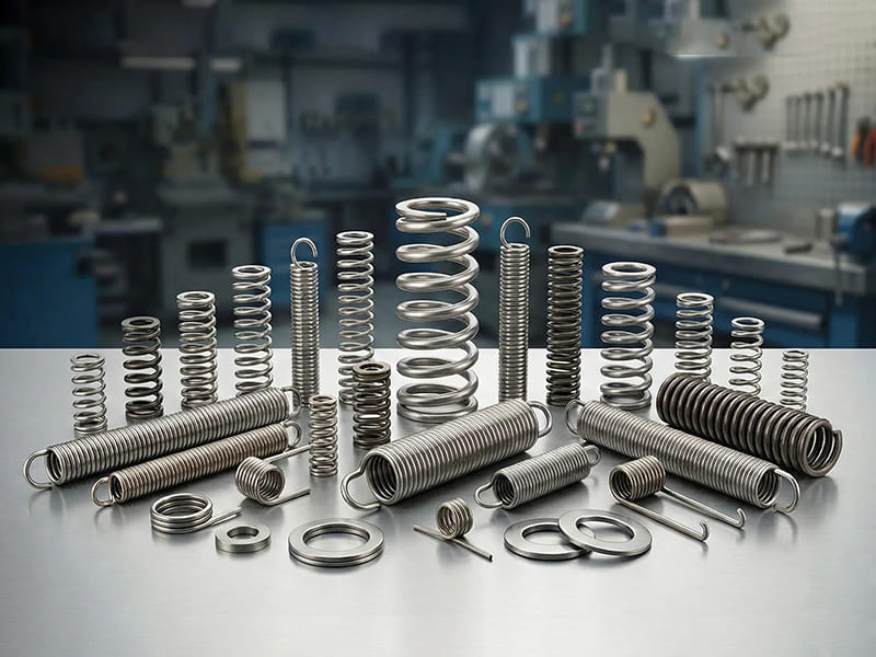
Springs are among the most deceptively simple components in mechanical design. They’re inexpensive, standardized, and widely available — which is exactly why engineers underestimate how badly a wrong selection can go. A compression spring chosen for free length alone without checking solid height clearance, a torsion spring installed in the wrong winding direction, an extension spring with undersized hooks in a high-cycle application — these aren’t exotic failure modes. They’re the kinds of problems that show up in production, not on a drawing review.
This article goes beyond listing types of springs. The goal is to connect spring type, material, geometry, and fatigue requirements to actual application decisions. Whether you’re specifying a return spring for a valve actuator, selecting a disc spring for a bolted joint preload, or choosing between cold-coiled and hot-coiled manufacturing for a heavy-load application — the selection logic matters as much as the catalog number.
What Is a Spring and How Does It Actually Work?
A spring is a mechanical element that stores elastic energy under load and releases it predictably when that load is removed. What makes springs useful in real designs is the controlled relationship between force and displacement — which can be tuned by changing wire diameter, coil geometry, material, or end configuration.
Hooke’s Law and When It Applies
The fundamental relationship is F = kx, where F is applied force, k is the spring rate (stiffness), and x is displacement from the free position. For linear springs — the majority of standard coil springs — k remains constant across the working range, making force and deflection directly proportional and predictable.
Not all springs follow this relationship, and for good reason. Progressive-rate springs become stiffer as they compress, which is exactly what automotive suspension engineers want: soft initial response for ride comfort, increasing stiffness at higher deflections to prevent bottoming out. Variable-pitch coil springs and conical springs achieve this without adding complexity to the surrounding mechanism.
In practical design work, two points consistently get ignored. First, Hooke’s Law only applies within the elastic range — operating a spring beyond its rated travel causes permanent set and changes the effective spring rate. Second, the installed condition matters as much as the free length. A spring that looks right on paper may have insufficient remaining travel for its working stroke once the assembly preload is accounted for.
The Four Main Types of Springs in Engineering
In engineering practice, spring classification starts with load direction — not appearance. Matching the spring type to how force is actually applied in the assembly is the first and most important selection decision.
Compression Springs
Compression springs are the most widely used type. They carry compressive axial loads, shortening under force and pushing back toward their free length. Standard open-coil helical compression springs are versatile, well-understood, and available in a huge range of dimensions and materials.
Key engineering considerations that often get skipped:
Slenderness ratio and buckling: When free length exceeds roughly 4× the coil outer diameter, buckling risk increases substantially. Guides or support posts are often required — not just recommended — to keep the spring aligned under load.
Solid height clearance: Working length at maximum compression must exceed solid height (number of active coils × wire diameter) by an adequate margin. Springs compressed to solid height lose their spring function entirely and transmit direct compressive loads to the surrounding structure, which is usually not the design intent.
End conditions: Closed and ground ends provide flat bearing surfaces and reduce the tendency for spring ends to dig into mating components. Open ends are adequate for light loads but introduce variable contact and increased friction in guided applications.
Typical applications: valve return mechanisms, punch press tooling, shock absorption buffers, push-button returns, and virtually any application requiring a controllable resisting force over a defined axial stroke.
Extension (Tension) Springs
Extension springs carry tensile loads — they resist being stretched and return to their free length when the load is removed. Most extension springs are wound with an initial tension: a built-in preload that must be overcome before the spring begins to extend. This is useful for maintaining a fixed return force in mechanisms that need the spring to stay taut even when not loaded.
The dominant failure mode in extension springs isn’t in the coils — it’s at the hooks or loops. Stress concentration at hook bends can be 2–3× higher than in the coil body, which is where fatigue cracks initiate in high-cycle applications. Engineers specifying extension springs for duty cycles above 10⁶ cycles should either use extended hooks that shift the bend radius outward, or specify springs without hooks (machine-looped ends or threaded inserts) and use external attachment hardware.
Typical applications: garage door counterbalance systems, spring-loaded latches, tension control in web handling equipment, and linkage return mechanisms.
Torsion Springs
Torsion springs deliver torque rather than linear force. They twist about their coil axis, with load applied to the legs (straight extensions from the coil body). As the spring is wound — or unwound, depending on configuration — it applies a rotational restoring force.
Two installation details that frequently cause problems:
Winding direction: Torsion springs must be wound in the correct direction relative to the applied torque. Loading a torsion spring in the opening direction increases coil diameter (reducing stress), while loading in the closing direction decreases coil diameter and increases stress concentration. Getting this wrong reduces fatigue life significantly.
Leg stress concentration: The transition between the coil body and the leg is a high-stress zone. Sharp bends at leg attachment points are a common fatigue initiation site. Generous bend radii and controlled leg geometry substantially improve service life.
Typical applications: door and lid hinges, clip mechanisms, clothespins, return springs in levers and pedals, and mechanism reset springs in consumer devices.
Constant Force Springs
Constant force springs are flat strip springs wound into a tightly coiled roll. As the strip uncoils, the bending moment remains nearly constant regardless of how much strip has been extended — producing an essentially flat force-displacement curve over a wide range of travel.
This characteristic is genuinely useful in applications where a traditional coil spring’s increasing force with deflection creates problems. Cable management systems, retractable cord reels, and counterbalance mechanisms for vertical loads all benefit from constant force behavior. The trade-off is that constant force springs are less spatially efficient than coil springs when unextended and require specific housing geometry to function correctly.
| Spring Type | Load Mode | Caraterísticas principais | Primary Applications |
|---|---|---|---|
| Compression | Axial compressive | Versatile, widely available | Buffers, valves, shock absorption |
| Extensão | Axial tensile | Initial tension preload | Doors, linkages, counterbalances |
| Torsion | Rotational | Torque output | Hinges, clamps, lever returns |
| Constant force | Linear over travel | Near-constant output force | Retractors, cable management |
Special Spring Types Worth Knowing
Standard helical springs don’t solve every problem. Several specialized designs consistently outperform conventional springs in specific engineering constraints — and they’re frequently overlooked until late in the design cycle when space or load problems become apparent.
Disc (Belleville) Springs
Disc springs are conically formed circular discs that carry very high axial loads in minimal axial space. The load-deflection behavior is highly nonlinear and can be tuned by changing the disc’s height-to-thickness ratio (h/t). At h/t ≈ 0.4, the spring behaves approximately linearly; at h/t > 1.4, the curve becomes S-shaped with a region of nearly constant force.
More practically useful is the stacking behavior. Disc springs stacked in series (cone-up, cone-down, alternating) increase total travel while maintaining load. Stacked in parallel (all cones facing the same direction), they multiply load capacity at the same deflection. Combining series and parallel stacking allows engineers to achieve specific load-deflection targets within a tight package.
These springs are standard in bolted joint preloading applications — particularly where vibration would cause conventional bolt tension to relax over time. The spring maintains compressive load across the gasket or joint interface through thermal cycling and vibration without requiring periodic retorquing.
Wave Springs
Wave springs achieve compression spring function at substantially reduced solid height — typically 50% of an equivalent coil spring. The undulating wave form distributes load more uniformly around the circumference, reducing friction against housing walls in guided applications.
In precision mechanisms where stack height is a primary packaging constraint — bearing preload systems, electromechanical actuators, medical device components — wave springs regularly enable designs that standard coil springs make impossible. The design trade-off is load capacity: wave springs generally carry lower peak loads than equivalent-diameter coil springs, which makes careful load analysis important before substituting.
Leaf Springs
Leaf springs operate in bending rather than torsion or compression. A single leaf or stack of leaves acts as a cantilevered or simply-supported beam, providing high load capacity combined with structural functionality. In vehicle suspension applications, the spring also serves as a lateral locating member — combining two structural functions in one component.
For multi-leaf assemblies in heavy vehicle suspensions, the progressive stiffness behavior (softer when lightly loaded, stiffer under heavy load) is achieved through variable leaf lengths and interleaf friction. Modern mono-leaf composite springs (fiberglass/epoxy) achieve similar performance at significantly reduced weight — relevant in commercial vehicle applications where unsprung mass directly affects payload efficiency.
Spiral (Clock) Springs
Spiral springs store rotational energy in a flat coiled strip, releasing torque over an angular displacement range. Unlike torsion springs, which operate over limited angular deflection (typically under 360°), spiral springs can operate over multiple full rotations — making them suitable for retractable mechanisms and instruments requiring consistent torque over extended angular travel.
| Design Constraint | Better Alternative to Standard Coil |
|---|---|
| Very high load, minimal axial space | Disc / Belleville spring |
| Tight stack height limit | Wave spring |
| Combined spring + structural function | Leaf spring |
| Rotational energy over large angular travel | Spiral / clock spring |
How to Select the Right Spring: Engineering Decision Framework
Spring selection involves more variables than most catalog sheets acknowledge. Working through these in sequence produces more reliable results than starting with a geometry and working backward to justify it.
Step 1: Define Load Direction and Motion Type
The load direction determines which spring type is even applicable. Axial compressive load — compression spring. Axial tensile load — extension spring. Rotational torque — torsion spring. Constant force over large travel — constant force spring. Getting this wrong at step one creates problems that no amount of subsequent optimization can fix.
Also define whether the loading is static (constant load, no cycling) or dynamic (cycling between load states). Static applications are generally forgiving — yield strength governs. Dynamic applications require fatigue analysis — yield strength alone is insufficient.
Step 2: Establish Space Constraints
Available axial height and radial space directly constrain spring geometry. For compression springs in guided applications, the installed length, solid height, and working stroke must all fit within the housing travel. Maximum outer diameter and minimum inner diameter define what coil geometry is possible.
When standard coil geometry won’t fit — particularly when axial height is the binding constraint — wave springs and disc springs should be evaluated before resorting to custom coil spring geometries. In most cases, these alternatives resolve the space problem more reliably than trying to squeeze a coil spring into insufficient height.
Step 3: Calculate Required Spring Rate
Spring rate k (N/mm or lb/in) defines the force-deflection relationship: k = F / x. The required rate comes from knowing both the force needed and the allowable deflection at that force. Common errors at this stage:
- Calculating k at one operating point without checking whether the spring also meets requirements at the other end of the stroke
- Ignoring preload — the spring may need to provide a minimum force even at its free length in the assembly
- Forgetting that spring rate changes as springs are stacked (series reduces k, parallel increases k)
Once k is established, wire diameter, coil diameter, and number of active coils can be determined from standard spring design equations or design software.
Step 4: Specify Fatigue Life and Safety Factor
Fatigue governs spring selection in any application with more than a few thousand load cycles. Industry-standard fatigue design for springs categorizes applications roughly as:
- Static or low cycle (< 10⁴ cycles): Yield strength controls; fatigue analysis often unnecessary
- Medium cycle (10⁴ to 10⁶ cycles): Fatigue must be checked; surface condition and stress concentration matter
- High cycle (> 10⁶ cycles): Fatigue governs completely; surface finish, residual stress from shot peening, and stress concentration factors at hooks or legs are all design inputs
Safety factors of 1.5× are a practical minimum for dynamic applications; 2.0–3.0× is appropriate when load uncertainty is significant or consequences of failure are high. Automotive suspension springs, valve springs in engines, and clutch return springs typically see 10⁷ to 10⁸ cycles across their service life — fatigue life must be calculated explicitly, not assumed.
Spring Selection Checklist
| Fator | Key Questions |
|---|---|
| Load direction | Compressive, tensile, or torsional? Static or dynamic? |
| Space constraints | Maximum axial height, OD, ID? Guided or unguided? |
| Force and travel | Required force at minimum and maximum deflection? Working stroke? |
| Spring rate | What k is needed? Linear or progressive? |
| Fatigue life | Expected cycle count? Required safety factor? |
| Material | Temperature range? Corrosive environment? Conductivity needed? |
| Manufatura | Standard catalog or custom? What tolerances are required? |
Spring Materials: Properties and Selection Logic
Material selection for springs is a performance-cost trade-off governed by fatigue requirements, operating temperature, and environmental exposure.
High-Carbon Spring Steel (ASTM A228, EN 10270-1)
Patented and cold-drawn hard-drawn wire is the backbone of commercial spring manufacturing. Good fatigue resistance at an economical price point — tensile strength for 1 mm wire runs approximately 2,000–2,200 MPa depending on grade, dropping with increasing wire diameter. Surface quality directly affects fatigue life: bright drawn wire with minimal seam defects outperforms standard hard-drawn wire in cycle-sensitive applications.
The limitation is corrosion. Uncoated carbon steel springs rust rapidly in humid, outdoor, or aqueous environments. Zinc or phosphate coatings provide modest protection; for more aggressive environments, either stainless steel or a dedicated protective coating is required.
Stainless Steel (302/304, 316, 17-7 PH)
Grades 302/304 cover most general-purpose stainless spring requirements — reasonable fatigue resistance with excellent atmospheric corrosion resistance. Grade 316 adds molybdenum for improved chloride resistance, appropriate for marine, food processing, and chemical environments.
For high-strength stainless spring applications — where the yield strength of 302/304 is insufficient — 17-7 PH (precipitation-hardening stainless) in CH900 condition achieves tensile strengths of 1,650–1,900 MPa with good corrosion resistance. This grade is standard for aerospace and medical device springs where both corrosion resistance and high fatigue strength are required simultaneously.
The cost premium over carbon steel is significant — roughly 3–5× for standard grades — but the elimination of coating requirements and extended service life in corrosive environments often justifies the difference in lifecycle cost analysis.
Alloy Steel (Chrome-Silicon, Chrome-Vanadium)
Chrome-silicon (51CrSi4, SAE 9254) and chrome-vanadium (51CrV4) steels are the materials of choice when maximum fatigue life in clean environments is the requirement. Engine valve springs, clutch springs, and high-performance suspension springs consistently use these grades.
Chrome-vanadium offers superior fatigue resistance in the as-drawn condition and excellent toughness at the elevated temperatures seen in engine applications. Chrome-silicon provides the highest tensile strength among common spring wire grades — up to 2,100 MPa for small wire diameters — and is particularly effective when combined with shot peening to introduce beneficial compressive residual stress at the wire surface.
Copper Alloys (Phosphor Bronze, Beryllium Copper)
Copper-based spring materials are specified when electrical conductivity, magnetic neutrality, or resistance to saltwater corrosion drives the design. Phosphor bronze (C51000) offers good corrosion resistance and non-magnetic behavior — relevant for springs in instruments or assemblies near magnetic sensors. Beryllium copper (C17200) achieves spring-quality tensile strengths (1,100–1,400 MPa after age hardening) with excellent conductivity, making it the premium choice for electrical contact springs.
Both grades have lower fatigue resistance than steel and are substantially more expensive. They’re appropriate for niche applications, not as general substitutes for steel springs.
| Material | Tensile Strength (typical) | Resistência à fadiga | Resistência à corrosão | Custo |
|---|---|---|---|---|
| Hard-drawn carbon steel | 1,600–2,200 MPa | Bom | Pobres | Baixo |
| 302/304 stainless | 1,300–1,700 MPa | Moderado | Excelente | Alto |
| 17-7 PH stainless | 1,650–1,900 MPa | Bom | Excelente | Muito elevado |
| Chrome-vanadium alloy | 1,700–2,100 MPa | Excelente | Moderado | Médio |
| Bronze fosforoso | 700–1,000 MPa | Moderado | Excelente | Média-alta |
| Beryllium copper | 1,100–1,400 MPa | Moderado | Excelente | Muito elevado |
Manufacturing Considerations: What Designers and Buyers Often Miss
The manufacturing process builds performance into a spring — or takes it away. Understanding which process decisions matter helps both designers writing specifications and buyers evaluating quotes.
Cold Coiling vs Hot Coiling
Cold coiling is standard for wire diameters below approximately 16 mm. The process work-hardens the wire surface as it’s coiled, contributing to the final tensile strength. Dimensional accuracy is excellent — spring rate tolerances of ±5% and free length tolerances of ±0.5 mm are standard for quality cold-coiled springs. Post-coiling stress relief (typically 200–250°C for carbon steel) removes coiling stresses without reducing hardness significantly.
Hot coiling is used for large wire diameters (typically above 16 mm) and for springs requiring complex geometry that cold-coiling tooling can’t achieve. The bar or rod stock is heated above the recrystallization temperature, coiled on a mandrel, then quenched and tempered to final hardness. Dimensional accuracy is lower than cold coiling — free length tolerances of ±1–2 mm are typical before final grinding — but the process can handle material cross-sections that cold coiling equipment simply can’t manage.
End Finishing and Grinding
Closed and ground ends on compression springs require face grinding to produce flat, perpendicular bearing surfaces. The grinding process removes a small amount of material from each end — important to account for in total coil count and free length specification. Improper grinding introduces stress concentrations at the wire surface and can locally reduce wire cross-section, reducing load capacity at precisely the highest-stress location.
CNC spring grinding machines control face parallelism (typically within 1° for standard commercial springs, 0.5° for precision grades) and ensure consistent solid height across a production lot. Specifying the required parallelism tolerance on drawings avoids receiving springs that meet free length and rate requirements but rock under load due to non-parallel ends.
Shot Peening and Its Effect on Fatigue Life
Shot peening introduces beneficial compressive residual stress into the wire surface layer (0.1–0.3 mm depth for typical wire diameters). This compressive layer must be overcome before tensile fatigue stresses can initiate cracks, effectively raising the fatigue endurance limit. For high-cycle applications — engine valve springs, suspension springs, precision instrument springs — shot peening after coiling and before stress relief can improve fatigue life by 20–50% at the same stress level.
The process is well-established but must be specified explicitly. Standard commercial spring quotes don’t include shot peening unless it’s called out. For springs with duty cycles above 10⁶ cycles in high-stress applications, it’s worth the modest cost addition.
Custom vs Standard Catalog Springs
Standard catalog springs make sense when the application is reasonably common, lead time and cost are priorities, and performance requirements don’t exceed catalog limits. They’re the right answer for most secondary mechanism springs, returns, and buffers where custom design won’t provide meaningful performance improvement.
Custom springs are justified when: the required combination of rate, free length, and outer diameter isn’t available in standard catalogs; the material must be non-standard (titanium alloys for aerospace weight reduction, Inconel for high-temperature service); tolerances are tighter than commercial standard; or fatigue life requirements exceed what stock springs are designed for. Custom manufacturing lead times of 4–8 weeks are typical for initial production lots; tooling costs are generally modest for standard coil geometries.
Common Spring Selection Mistakes and How to Avoid Them
Most spring failures in production don’t trace back to manufacturing defects — they come from specification errors made during design. Three mistakes account for the majority of field failures:
Operating too close to solid height or maximum extension: Designers often size the working stroke without leaving adequate margin from the spring’s physical limits. A compression spring compressed to within 1 mm of solid height under peak load will occasionally reach solid height due to load variation, manufacturing tolerances, or assembly variation — and transmit direct load to the structure in a way the design never accounted for. Build in at least 10–15% of free length as clearance above solid height at maximum deflection.
Underspecifying fatigue life requirements: A spring that meets force and rate requirements but is rated for 10⁵ cycles in an application that actually sees 10⁷ cycles will fail prematurely — typically in 3–6 months of production use. Specifying expected cycle count on the drawing forces the spring manufacturer to select appropriate wire grade, surface treatment, and safety factor to achieve that life.
Substituting standard coil springs into space-constrained designs: Forcing a standard coil spring into a housing that’s 20% too short creates either buckling risk (spring too slender) or solid-height clearance problems (spring too compressed). Wave springs and disc springs exist precisely to resolve this constraint — evaluating them early eliminates the compromise.
Exemplos de Aplicação Real
Automotive Suspension: Progressive Rate Coil Springs
Modern automotive coil spring suspensions use variable-pitch springs — compression springs with non-uniform coil spacing that produce a progressive spring rate. At low deflection (light load, smooth roads), the closely spaced coils contact their neighbors and become inactive, leaving only the widely spaced coils working at a lower effective rate for ride comfort. Under heavy loading or large suspension travel, all coils engage and the effective rate increases. This behavior is achieved through coil geometry alone, without any added complexity.
Material: chrome-silicon alloy steel (SAE 9254), shot-peened, with epoxy powder coat for corrosion protection. Target fatigue life: 10⁷ cycles minimum at rated load cycling.
Industrial Press Tooling: Nitrogen Gas Springs vs Compression Springs
In metal stamping and progressive die tooling, die springs (heavy-duty compression springs) have traditionally provided blank-holding and stripper-plate force. For applications requiring high force in minimal installation height, nitrogen gas springs are increasingly used. A gas spring with 50 mm stroke provides essentially constant force throughout that travel — unlike a coil spring, whose force increases approximately linearly with compression.
For standard punch press applications, high-strength chrome-silicon die springs in standard color-coded force ranges (light, medium, heavy, extra-heavy per ISO/NAAMS standards) remain the economical default. Nitrogen gas springs justify their higher cost in applications where force uniformity across the stroke meaningfully improves part quality.
Precision Instrument: Wave Spring for Bearing Preload
In a compact optical instrument design, a bearing preload spring must fit within a 3 mm axial space between the bearing outer ring and housing shoulder, providing 120 N of preload force. A standard coil spring would require at least 8–10 mm of installation height to achieve this combination of load and deflection. A wave spring (stainless 302, single-turn with 4 waves) achieves the same 120 N at 1.5 mm deflection within a 2.8 mm solid height — fitting the constraint with margin remaining.
Conclusão
Understanding types of springs is the starting point, not the destination. Compression, extension, torsion, and constant-force springs cover the majority of applications — but selecting the right one requires working through load direction, space constraints, required spring rate, and fatigue life requirements in sequence, not picking based on visual familiarity. Special designs like disc springs, wave springs, and leaf springs solve specific engineering problems that standard helical springs can’t address efficiently.
Material selection adds another layer: carbon steel for cost-effective industrial use, stainless steel for corrosion resistance, alloy steel for maximum fatigue performance, copper alloys for conductivity or non-magnetic requirements. Manufacturing choices — cold vs hot coiling, shot peening, end grinding quality — build the final performance into the physical part. Treat springs as engineered components with quantifiable requirements, specify those requirements explicitly on drawings, and the probability of a spring becoming the failure point in your system drops substantially.
Perguntas frequentes
What are the main types of springs in mechanical engineering?
The four primary load types cover most applications: compression springs (axial compressive load), extension springs (axial tensile load), torsion springs (rotational torque), and constant force springs (near-constant output over large travel). Beyond these, disc springs, wave springs, leaf springs, and spiral springs address specific constraints around load density, space efficiency, or energy storage that standard helical types can’t meet as effectively.
Compression vs extension spring — which should I use?
The load direction in the application determines this. If the spring is compressed between two surfaces, use a compression spring. If two components pull apart and need to be returned, use an extension spring. The choice isn’t aesthetic — it’s governed by how the spring is mechanically loaded. Putting an extension spring in a compressive application creates installation and fatigue problems that no specification adjustment can fix.
How do I calculate the right spring rate?
Spring rate k = F / x, where F is the required force at deflection x. Calculate k at both ends of the working stroke to confirm the spring meets requirements throughout its travel range, not just at the nominal operating point. Wire diameter, coil diameter, and active coil count then determine k per standard helical spring design equations: k = (Gd⁴) / (8D³n), where G is the shear modulus of the material, d is wire diameter, D is mean coil diameter, and n is the number of active coils.
When should I use a wave spring instead of a coil spring?
Use a wave spring when axial installation height is a hard constraint that a coil spring can’t meet at the required load and deflection. Wave springs typically achieve the same load in 50% of the axial height of an equivalent coil spring. They’re particularly valuable in precision assemblies, bearing preload applications, and any design where adding axial length would require changing housing geometry, increasing product size, or reducing functional travel.
Can springs be custom manufactured to precise specifications?
Yes. Custom coil spring manufacturing is well-established for non-standard combinations of rate, free length, outer diameter, wire diameter, material, or end configuration. CNC spring coilers produce custom springs with spring rate tolerances of ±3–5% and free length tolerances of ±0.3–0.5 mm for precision grades. Custom springs are justified when standard catalog options don’t meet combined dimensional and performance requirements — typically for specialized load paths, extreme environments, or high-cycle fatigue applications where off-the-shelf springs carry insufficient safety margin.


