
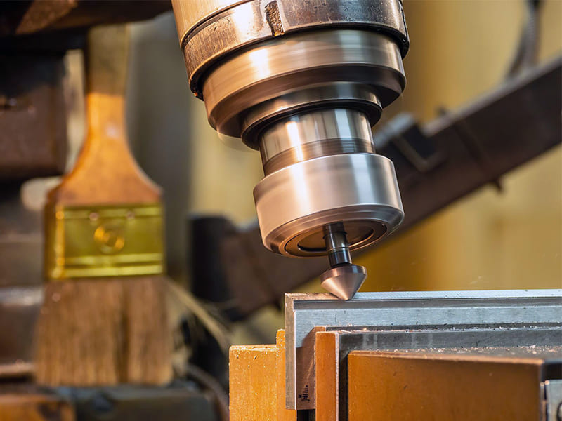
A drawing calls out “0.5 × 45° chamfer” on 36 hole edges. The machinist programs it, runs the batch — and 15% of parts fail inspection because the chamfer tool wore down mid-run on 316L stainless, producing chamfers that shrank from 0.5 mm to 0.3 mm by part forty. Meanwhile, the designer who specified it just wanted burr-free edges for assembly. The fix was simple: call out “break edges 0.2–0.5” on non-critical holes and reserve the dimensioned chamfer for the four press-fit bores that actually needed controlled lead-in. That change cut machining time by 20% and eliminated the inspection failures entirely.
Understanding what chamfering is in machining — and more importantly, when and how to specify it correctly — prevents exactly this kind of waste. Chamfering is a controlled machining operation that replaces a sharp 90° edge with a defined angled surface, most commonly specified by size and angle (e.g., 0.5 × 45°). This article covers why chamfers matter in production, how they’re dimensioned on drawings, CNC machining methods, material-specific behavior, size and angle selection, quality control, and when to use chamfers versus fillets or countersinks. Whether you’re a designer specifying edge treatments, an engineer programming CNC operations, or a buyer reviewing part quality, the goal is to treat chamfering as the engineering decision it actually is.
What Exactly Is Chamfering?
Chamfering refers to deliberately removing a sharp 90° edge by cutting a flat, angled surface between two intersecting faces. A chamfer replaces an idealized sharp corner — which is impractical to manufacture and inspect — with a controlled, measurable geometry.
The most common specification is distance × angle, such as 0.5 × 45°. While 45° dominates due to tool availability and simplicity, other angles serve specific needs. Shallower angles (30°) guide axial insertion. Steeper angles (60°) protect edges or manage coating flow.
Chamfer vs. Bevel
In precision machining, chamfer typically describes a small, functional edge feature defined as part of standard machining. Bevel refers to larger edge treatments, often in fabrication contexts like weld preparation. The terms overlap in casual use, but chamfer implies dimensional control and repeatability — which matters for CNC production.
Why Chamfering Matters in Machined Parts
Assembly and Insertion
One of the most practical reasons for chamfering is assembly guidance. Chamfered edges act as lead-ins that align shafts into bores, guide press-fit components, and improve thread engagement. In automated or high-volume assembly, even small misalignments cause jamming or cross-threading. A properly sized chamfer reduces insertion force and variability.
In our shop floor experience, adding a 1.0 × 45° chamfer to press-fit aluminum bores reduced assembly rejection rates by roughly 35% — without changing any tolerance on the bore itself.
Stress Reduction and Edge Protection
Sharp corners concentrate stress. Under cyclic loads, they become crack initiation sites. Chamfering smooths the transition between intersecting faces, reducing local stress intensity and lowering edge chipping risk. While fillets provide better stress reduction, chamfers offer a machinable, inspectable alternative — especially where sharp internal corners are unavoidable.
Safety, Handling, and Surface Treatment
Chamfers remove sharp edges that cause cuts during handling and assembly. They also improve coating and anodizing performance. Paint, plating, and anodize layers thin at sharp edges, leading to coating breakdown. Chamfered edges allow coatings to flow and adhere more uniformly, improving corrosion resistance and cosmetic consistency.
How to Dimension Chamfers on Drawings
Clear chamfer callouts prevent the most common source of mis-machining, inspection disputes, and rework in CNC production.
Common Methods
Distance × Angle (most common): “1 × 45°” — intuitive, easy to program and inspect. Dual-distance: “1 × 0.5” (two legs) — useful when the angle is non-standard or functionally driven. General notes: “ALL SHARP EDGES C0.5” or “BREAK ALL EDGES 0.2–0.5” — reduces drawing clutter but must be used carefully to avoid over-processing functional edges.
Chamfer vs. “Break Edge”
This distinction matters more than most designers realize. A chamfer is a defined geometric feature with measurable size and angle — use it when edge geometry affects assembly, stress, coating, or fit. A break edge is an edge condition requirement for safety or burr removal without controlling exact geometry.
One common pitfall we see: drawings that call out dimensioned chamfers on every edge when most only need a break-edge note. This forces machinists to program, execute, and inspect dozens of non-critical features — adding 15–25% to cycle time on complex parts. Specify chamfers where function demands them. Use break-edge notes everywhere else.
Drawing Standards
ISO and ASME (Y14.5) both support distance-angle and dual-distance callouts. The key principle across both: chamfers must be unambiguous, inspectable, and functionally justified.
How Is Chamfering Done in CNC Machining?
CNC Milling
Dedicated chamfer mills (V-tools) deliver the most stable, repeatable results for standard angles — the go-to choice for production runs. Ball end mills handle chamfers on contoured or 3D surfaces. Flat end mills can roll edges in simple cases but are sensitive to toolpath accuracy.
Consistent chamfers depend on toolpath strategy, depth control, and engagement. Poorly planned paths produce variable chamfer width, chatter marks, or over-cut edges — especially at corners or interrupted cuts. Design chamfers with tool accessibility in mind.
CNC Turning
External chamfers on shafts and shoulders and internal chamfers on bores and threaded holes integrate directly into the turning cycle. Turning-based chamfering produces excellent concentricity and surface continuity because the chamfer generates in the same setup as the diameter.
Manual vs. CNC
Manual chamfering (hand tools, deburring wheels) produces inconsistent size and angle with poor traceability. For precision parts, CNC chamfering is the only reliable approach — repeatable geometry, integrated into the machining cycle, with no secondary handling.
How Materials Affect Chamfer Machining
Aluminum (6061/7075)
Soft and ductile — easy to cut but prone to burr formation and edge rollover. Small chamfers may smear or collapse without sharp tools and controlled feeds. For precision parts, slightly oversizing chamfers accounts for material loss during deburring or anodizing.
Steel and Stainless Steel (304/316L)
Higher cutting forces and greater tool wear. Chamfering hardened or stainless steels wears the tool edge, causing chamfer width to shrink across long runs. Based on our production data, chamfer tool life on 316L stainless is roughly 40% shorter than on 6061 aluminum — requiring more frequent tool wear monitoring or scheduled changes.
Plastics (POM, PEEK, Nylon)
Thermoplastics may melt or smear at high cutting speeds. Brittle plastics chip instead of cutting cleanly. Small chamfers lose definition due to elastic recovery. Use larger, simpler chamfers with conservative parameters on plastic parts.
Selecting Chamfer Size, Angle, and Tooling
Size by Function
Deburring / safety: 0.2–0.5 mm is sufficient. Over-sizing adds cycle time without benefit. Assembly lead-in: 0.5–1.5 mm depending on part size and tolerance stack-up. Stress mitigation: Large enough to materially reduce edge stress — token chamfers offer little benefit. Surface treatment allowance: Oversize to remain functional after coating thickness buildup.
Angle Selection
45° balances lead-in, tool availability, and inspection simplicity. Shallower angles (30°) suit gentle axial insertion. Steeper angles (60°) protect edges but are more sensitive to tool wear and depth control.
Tooling
Dedicated chamfer mills give the most stable results. Match tool angle to chamfer angle to minimize depth sensitivity. Keep overhang short to reduce chatter. Account for tool wear in steel and stainless when holding tight chamfer tolerances.
Quality Control for Chamfers
Inspection Methods
Visual inspection catches obvious issues (sharp edges, burrs, inconsistency) but can’t verify size or angle. CMM measurement captures chamfer geometry via edge points — best for tight tolerances and traceability. Optical systems suit small chamfers and fragile materials. Go/No-Go gauges enable fast accept/reject checks in high volume.
Common Defects
Over-chamfering reduces bearing area and breaks tolerance stacks — often from depth sensitivity or tool wear. Under-chamfering leaves sharp edges, poor lead-in, and coating issues. Inconsistent width results from tool wear, variable corner engagement, or unstable paths.
Production Control
Program chamfers with tool-angle matching. Apply wear offsets for steel and stainless runs. Use first-article inspection to validate depth and path, then audit periodically. Define clear drawing intent — dimensioned chamfer vs. break edge — to prevent shop-floor misinterpretation.
Chamfer vs. Fillet vs. Countersink
Chamfer: Flat angled surface for edge control, assembly guidance, and general-purpose edge treatment. Easiest to machine and inspect. Fillet (radius): Curved transition for maximum stress reduction. Preferred for fatigue-critical corners but harder to machine internally. Countersink: Specialized chamfer for flush fastener seating at standardized angles (82°, 90°). Only use when required by fastener standards.
| Feature | Primary Purpose | Stress Reduction | Machinability | Typical Use |
|---|---|---|---|---|
| Chamfer | Edge control, lead-in | Moderate | Excellent | General edges, holes |
| Fillet | Stress reduction | Best | Moderate (poor internally) | Load-bearing corners |
| Countersink | Fastener seating | Limited | Good | Flat-head screws |
Decision logic: Choose chamfers for most general edges. Choose fillets where fatigue dominates and geometry allows. Choose countersinks only for fastener seating.
Conclusion
Chamfering is a functional engineering feature that directly improves assembly reliability, edge durability, handling safety, and surface treatment quality. Its impact is disproportionate to its size — when specified correctly. Sizes and angles should follow function (deburring, lead-in, stress, coating), not default values. Material behavior drives edge quality. Tool geometry and programming determine consistency. Inspection methods must match the chamfer’s functional risk.
The core principle: good chamfers are designed, machined, and verified as a system. When these steps align, chamfering becomes a low-cost lever for more stable machining, smoother assembly, and higher part quality. Need help specifying chamfers or optimizing edge treatments for your CNC project? [Contact our engineering team] for DFM review and precision machining support.
FAQ
What is the standard chamfer angle in machining?
45° is the most common — it balances assembly lead-in, tool availability, and inspection simplicity. However, 45° isn’t universal. Use 30° for gentle axial insertion, 60° for edge protection or coating flow. The correct angle follows function and assembly direction, not convention.
Is chamfering always necessary?
No. Chamfer where sharp edges create safety risks, assembly issues, stress concentration, or coating defects. For non-functional edges, a simple break-edge note (0.2–0.5 mm) is often sufficient and cheaper to execute. Over-specifying chamfers adds machining time and inspection burden without benefit.
Can chamfers replace fillets?
Sometimes. Chamfers partially reduce stress and are easier to machine and inspect, especially on internal corners. However, fillets provide smoother stress transitions and better fatigue performance. Choose chamfers when geometry, tooling, or inspection constraints make fillets impractical.
How small can a chamfer be machined reliably?
Below 0.2 mm, chamfers become difficult to control consistently — especially in aluminum (edge collapse) and steel (tool wear). If the intent is only to remove sharpness, specifying a break edge of 0.2–0.5 mm is more robust than calling out a very small dimensioned chamfer.
Does chamfering add significant cost?
When integrated into CNC toolpaths, chamfering adds minimal cost. Dedicated chamfer tools and programmed passes are efficient in production. Cost increases when chamfers are oversized, inconsistently defined, or require manual rework. Clear drawings and functional sizing keep chamfering a low-cost, high-value feature.


