
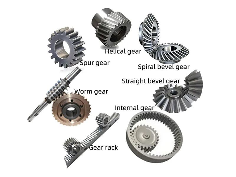
In mechanical systems, gear selection is a system-level engineering decision that affects performance, durability, noise, efficiency, and cost. Different gear types are not interchangeable—each is designed for specific combinations of load, speed, shaft orientation, and alignment tolerance, and the wrong choice can lead to vibration, wear, or unnecessary manufacturing complexity.
Understanding gear types helps engineers translate functional requirements into workable geometries and supports correct sizing, material choice, and durability analysis. From a practical standpoint, selecting the right gear type balances mechanical behavior, manufacturability, and cost to achieve reliable power transmission in real applications.
How Are Gears Classified in Engineering Practice?
In engineering, gear classification is not about naming parts—it is about organizing design constraints. Effective classification helps engineers quickly narrow down feasible solutions before detailed sizing, strength checks, or cost analysis. In practice, gears are classified along three complementary dimensions: shaft orientation, tooth geometry, and functional role.
Classification by Shaft Orientation
The first and most fundamental classification is based on how the input and output shafts are arranged:
-
Parallel shafts Both shafts run in the same direction. This category includes spur, helical, double helical, and internal gears. Parallel-shaft gears are mechanically efficient, easy to manufacture, and widely used in gearboxes, conveyors, and industrial drives.
-
Intersecting shafts Shafts cross at a defined angle, commonly 90°. Bevel gears dominate this category. They are used where direction changes are required, such as right-angle drives and differential systems.
-
Skew (non-parallel, non-intersecting) shafts Shafts neither intersect nor run parallel. Worm gears and crossed helical gears fall into this group. These configurations enable compact layouts but introduce sliding contact, which affects efficiency and heat generation.
Shaft orientation is usually the first filter in gear selection because it is dictated by system layout and mechanical architecture.
Classification by Gear Geometry and Tooth Form
Once shaft orientation is fixed, gear geometry further refines selection:
-
Straight vs angled teeth Straight teeth (e.g., spur gears) engage abruptly and are simple to machine. Angled teeth (e.g., helical gears) provide smoother engagement, higher load capacity, and lower noise, at the cost of axial forces and manufacturing complexity.
-
External vs internal gears External gears mesh with other external gears, while internal gears mesh inward-facing teeth. Internal gears are common in planetary gear systems, enabling compact designs and favorable load sharing.
This classification highlights how tooth form influences contact mechanics, noise, and load distribution.
Classification by Function
Finally, gears are classified by what they are intended to do within the system:
-
Speed increase or reduction Most gear trains modify rotational speed to match motor output with load requirements.
-
Torque multiplication Reduction gears increase torque at the expense of speed, critical in heavy-duty and precision motion systems.
-
Linear motion conversion Rack-and-pinion systems convert rotary motion into linear motion, common in CNC machines and automation equipment.
This functional view connects gear selection directly to system-level performance goals rather than geometry alone.
Together, these three classification layers form a practical decision framework. Engineers typically move from shaft orientation → gear geometry → functional optimization, ensuring that subsequent analysis and manufacturing choices are grounded in the correct gear family from the outset.
What Are the Most Common Types of Gears and How Do They Work?
In engineering practice, a small number of gear types account for the majority of mechanical power-transmission systems. While they may appear interchangeable at a high level, each type embodies distinct contact mechanics, load paths, and manufacturing implications. Understanding how they work—and where they fit—is essential for correct selection.
Spur Gears (Parallel Shaft, Straight Teeth)
Working principle: Spur gears transmit motion between parallel shafts using straight teeth that engage across the full face width at once. Power is transferred through rolling contact along the line of action.
Преимущества: They offer very high efficiency, simple geometry, and the lowest manufacturing cost among gear types. Tooth geometry is easy to inspect and control, making spur gears ideal for precision applications at moderate speeds.
Ограничения: Because engagement is abrupt, spur gears generate impact loading and noise at higher speeds. They are less tolerant of misalignment and vibration.
Типичные применения: Industrial gearboxes, conveyors, low-speed reducers, and positioning mechanisms where noise is not the primary constraint.
Helical Gears
Working principle: Helical gears use angled teeth, causing engagement to occur gradually and progressively across the tooth face. Multiple teeth share the load at any given time.
Key performance characteristics: The angled engagement significantly reduces noise and vibration and increases load-carrying capacity compared with spur gears. However, this geometry generates axial thrust forces, which must be absorbed by bearings or compensated through paired (double-helical) designs.
Типичные применения: Automotive transmissions, high-speed industrial drives, compressors, and systems where smooth operation and durability are critical.
Bevel Gears (Intersecting Shafts)
Working principle: Bevel gears transmit power between intersecting shafts—most commonly at 90°—using conical tooth geometry.
-
Straight bevel gears are simpler but generate more noise.
-
Spiral bevel gears provide smoother engagement and higher load capacity at increased manufacturing complexity.
Performance considerations: Bevel gears enable compact directional changes but require precise alignment and accurate machining to ensure correct tooth contact.
Типичные применения: Right-angle gearboxes, automotive differentials, and angular power-transfer systems.
Worm Gears
Working principle: Worm gears consist of a screw-like worm driving a worm wheel through sliding contact, rather than pure rolling.
Key characteristics: They provide very high reduction ratios in a single stage and can exhibit self-locking behavior, preventing back-driving under load. The trade-off is lower efficiency and significant heat generation due to sliding friction.
Типичные применения: Lifts, conveyors, indexing mechanisms, and systems where compact reduction or holding torque is required.
Rack and Pinion
Working principle: A rotating pinion gear meshes with a linear rack, converting вращательного движения в линейное (or vice versa).
Performance advantages: This configuration offers direct, predictable motion with minimal backlash when properly designed.
Типичные применения: CNC machines, linear actuators, steering systems, and precision positioning equipment.
Across these gear types, the unifying principle is clear: gear geometry defines how forces flow, how motion is transferred, and how reliably the system performs. Selecting the correct type is not about preference—it is about matching mechanical behavior to application requirements.
What Are Advanced and Specialized Gear Types Used in Industry?
Beyond basic spur, helical, and bevel gears, many industrial systems rely on advanced and specialized gear types to achieve higher power density, compact layouts, or improved noise and durability performance. These gears are typically selected not for simplicity, but for системная оптимизация where space, load, and reliability constraints dominate.
Planetary (Epicyclic) Gear Systems
Working principle: Planetary gear systems consist of a central sun gear, multiple planet gears, an internal ring gear, and a carrier. Torque is transmitted through multiple parallel load paths, with each planet sharing a portion of the load.
Инженерные преимущества: This load-sharing mechanism enables exceptionally high power density and compact size compared with parallel-shaft gear trains. Planetary systems also provide flexible speed ratios by fixing different members (sun, ring, or carrier).
Типичные применения: Automatic transmissions, servo gearboxes, robotics, aerospace actuators, and wind turbine drivetrains—anywhere high torque must be transmitted in limited space.
Internal Gears
Working principle: Internal gears have teeth cut on the inside diameter of a ring. They typically mesh with external gears rotating in the same direction.
Инженерное значение: Internal gears enable compact, coaxial layouts and reduced sliding velocity at the tooth contact compared with external gear pairs. They are fundamental components of planetary gear systems, where they act as the ring gear.
Типичные применения: Planetary gearboxes, compact reducers, and precision motion systems requiring minimal envelope size.
Hypoid and Spiral Bevel Gears
Working principle:
-
Spiral bevel gears transmit power between intersecting shafts using curved teeth for smoother engagement.
-
Hypoid gears extend this concept by allowing shaft offset, meaning the axes do not intersect.
Инженерные преимущества: These gears offer superior noise, vibration, and harshness (NVH) performance and higher load capacity compared with straight bevel gears. The offset in hypoid gears allows lower driveshaft placement and improved packaging.
Trade-offs: The sliding contact increases lubrication demands and manufacturing complexity, requiring high-precision machining and controlled heat treatment.
Типичные применения: Automotive differentials, heavy-duty drivetrains, and high-performance right-angle transmissions.
Miter and Zerol Gears
Working principle:
-
Miter gears are a special case of bevel gears with a 1:1 ratio, typically at 90°.
-
Zerol gears combine straight and spiral bevel characteristics, offering curved teeth without axial thrust.
Engineering role: These gears are selected for specific angle transmission requirements where balance, symmetry, or assembly simplicity is important.
Типичные применения: Indexing mechanisms, instrumentation, and compact angular drives with moderate load requirements.
In practice, advanced gear types are chosen to solve layout, load, and performance problems that basic gears cannot. For engineers and procurement teams, understanding these specialized options enables smarter trade-offs between power density, manufacturability, cost, and long-term reliability.
How Do Gear Geometry and Design Parameters Affect Performance?
Gear performance is not determined by gear type alone. Geometry and design parameters control how loads are transmitted, how smoothly teeth engage, and how long the gear set survives in service. In many applications, these parameters matter more than the nominal gear classification.
Tooth Profile and Pressure Angle
Most modern gears use an involute tooth profile because it maintains a constant velocity ratio even with small center-distance variations. This makes involute gears tolerant to manufacturing and assembly errors—an essential advantage in real-world gearboxes.
Сайт pressure angle (commonly 20°, sometimes 14.5° or 25°) defines the direction of force transmission between meshing teeth. Increasing the pressure angle:
-
Raises load-carrying capacity by thickening the tooth root
-
Improves resistance to bending failure
-
Increases radial forces, which place higher loads on bearings
Lower pressure angles reduce bearing loads and noise but limit torque capacity. From an engineering standpoint, pressure angle selection is always a trade-off between strength, efficiency, and system stiffness, not a default choice.
Module, Pitch, and Contact Ratio
Сайт module (or diametral pitch) sets the overall size of the gear teeth. Larger modules increase tooth thickness and bending strength but also increase gear size, mass, and cost. Smaller modules allow compact designs but demand tighter tolerances and higher material quality.
Equally important is the contact ratio, which describes how many tooth pairs are in contact during meshing:
-
A contact ratio slightly above 1 means load transfers from one tooth pair to the next
-
Higher contact ratios (>1.5) improve load sharing, smoothness, and noise behavior
Helical gears naturally achieve higher contact ratios than spur gears, which explains their superior NVH performance at the cost of axial thrust.
Noise, Vibration, and Wear Considerations
Noise, vibration, and wear are direct consequences of how gear teeth engage. Abrupt engagement, poor profile accuracy, or low contact ratio leads to dynamic loading and tonal noise. Sliding velocity, surface finish, and lubrication regime then govern wear and efficiency.
From an engineering perspective, quiet and durable gear operation is achieved not by “adding safety margin,” but by optimizing geometry—tooth profile accuracy, appropriate pressure angle, sufficient contact ratio, and controlled surface finish.
In practice, gear geometry parameters form a cause-and-effect chain: geometry defines force paths → force paths define vibration and stress → vibration and stress define noise, efficiency, and service life. Understanding this chain allows engineers to tune performance without unnecessary complexity or cost.
How Do Materials and Heat Treatment Influence Gear Performance?
Gear geometry defines how forces are transmitted, but materials and heat treatment determine whether a gear can survive those forces over time. From a manufacturing and reliability standpoint, material selection and surface treatment are among the most decisive factors in gear performance.
Common Gear Materials
-
Легированные стали (e.g., carburizing or through-hardening grades) are the dominant choice for industrial gears due to their high strength, fatigue resistance, and heat-treatment compatibility. They are suitable for moderate to very high loads and long service life requirements.
-
Нержавеющие стали are used when corrosion resistance is critical. While generally lower in load capacity than alloy steels, they perform well in food processing, medical equipment, and corrosive environments where durability must be balanced with environmental resistance.
-
Алюминиевые сплавы offer low weight and good machinability but limited wear resistance. They are typically used in light-duty or high-speed applications where inertia reduction is more important than torque capacity.
-
Инженерные пластмассы (such as nylon or POM) are selected for low noise, self-lubrication, and cost efficiency. Their load capacity is limited, but they are effective in consumer products, office equipment, and light automation.
Material choice directly affects strength, wear behavior, noise, and manufacturability, making it a core design decision rather than a secondary detail.
Термообработка и поверхностное упрочнение
Heat treatment is what allows gears—especially steel gears—to meet demanding load and life requirements.
-
Цементация produces a hard, wear-resistant surface with a tough core, making it ideal for high-load, fatigue-critical gears.
-
Закалка и отпуск increase overall strength and hardness, suitable for medium-load gears with simpler manufacturing routes.
-
Азотирование creates a hard surface layer with minimal distortion, advantageous for precision gears and tight tolerance assemblies.
These treatments significantly improve wear resistance, contact fatigue life, and load capacity, but they also introduce trade-offs in cost, distortion control, and process complexity.
From a manufacturing perspective, optimal gear performance comes from matching material and heat treatment to the load spectrum, speed, and required service life—not from selecting the hardest option by default. Proper alignment between design intent and manufacturing capability is what ultimately delivers reliable, cost-effective gear systems.
How Are Different Types of Gears Manufactured?
Gear performance is inseparable from how the gear is made. Manufacturing method determines achievable accuracy, surface integrity, cost, and scalability—often more decisively than nominal gear type. From a CNC machining and custom manufacturing perspective, understanding these processes is critical.
Gear Cutting Methods
The majority of gears begin with gear cutting, where tooth geometry is generated rather than merely shaped.
-
Фрезерование червячной фрезой is the most widely used method for external gears. A rotating hob progressively generates the involute tooth form, offering high productivity, good accuracy, and excellent repeatability. It is well suited for spur and helical gears in medium to large batches.
-
Долбление uses a reciprocating cutter and is especially valuable for internal gears and shoulder-constrained geometries that cannot be hobbed. It is slower than hobbing but far more flexible in terms of geometry.
-
Фрезерование is typically used for prototypes, large-module gears, or low-volume custom parts. While less efficient and less accurate than hobbing or shaping, CNC milling offers maximum design freedom and fast iteration during development.
The choice among these methods reflects a trade-off between geometry accessibility, accuracy, and production volume.
Gear Grinding and Finishing
For high-performance gears, cutting alone is not sufficient. Gear grinding is applied after heat treatment to restore accuracy and improve surface quality.
Grinding enables:
-
Tight tolerance control (higher gear accuracy grades)
-
Улучшенный tooth profile and lead accuracy
-
Снижено noise, vibration, and contact stress
Finishing processes such as honing or lapping further refine surface texture, directly affecting NVH behavior and service life. These steps add cost but are essential in automotive, aerospace, and precision industrial gearboxes.
Особенности механической обработки CNC
In CNC-based gear manufacturing, performance outcomes depend heavily on tolerance strategy and production intent.
-
Tolerance control must account for heat-treatment distortion, fixturing repeatability, and inspection capability—not just nominal dimensions.
-
Batch production favors dedicated tooling and optimized cutting paths to reduce unit cost.
-
Custom or low-volume gears prioritize flexibility, quick setup, and close collaboration between design and manufacturing to balance cost and performance.
From a manufacturing standpoint, gear quality is not defined by cutting method alone, but by the entire process chain—cutting, heat treatment, finishing, and inspection. Successful gear production aligns these steps with the intended application, ensuring that manufacturing effort translates directly into measurable performance and reliability.
How Do Engineers Choose the Right Type of Gear for an Application?
Selecting a gear type is a многофакторное инженерное решение, not a catalog lookup. Experienced engineers follow a structured decision process that balances performance requirements with manufacturing and lifecycle constraints. The goal is not to find a “best” gear, but the most appropriate gear for the system.
Load, Speed, and Torque Requirements
The first decision layer is mechanical demand. Engineers assess torque level, load spectrum (steady vs shock), and operating speed. High-torque, low-speed applications often favor spur, helical, or planetary gears due to their load capacity and efficiency. High-speed systems place greater emphasis on dynamic behavior and contact smoothness, which pushes designs toward helical, spiral bevel, or precision-ground gears.
Load direction and reversibility also matter. For example, worm gears may be attractive for high reduction and holding torque, but their lower efficiency and heat generation make them unsuitable for continuous high-power duty.
Space, Noise, and Efficiency Constraints
Once load feasibility is confirmed, system constraints narrow the options. Available envelope size and shaft orientation immediately eliminate many gear families. Compact layouts often point to planetary or internal gear systems, while right-angle drives require bevel or hypoid gears.
Noise and vibration constraints further refine selection. Spur gears may be mechanically sufficient but unacceptable in applications with strict NVH limits. Helical or spiral gears are chosen not because they are “better,” but because smoother engagement and higher contact ratio reduce excitation forces. Efficiency targets also matter: sliding-heavy designs (e.g., worm gears) trade efficiency for compactness or self-locking behavior.
Cost, Manufacturability, and Maintenance
The final decision layer is economic and operational. Gear types differ significantly in manufacturing complexity, tolerance sensitivity, and finishing requirements. A gear that performs perfectly on paper may be impractical if it requires grinding, exotic materials, or tight alignment beyond production capability.
Engineers also consider maintenance access, lubrication needs, and service life expectations. Simple spur or helical gears are easier to inspect and replace, while specialized systems may reduce size but increase maintenance complexity.
In practice, gear selection resembles a decision matrix: mechanical feasibility → spatial and performance constraints → manufacturing and lifecycle cost. The right gear type is the one that satisfies all three layers simultaneously—delivering required performance without exceeding manufacturing capability or budget.
Summary: Key Engineering Takeaways on Types of Gears
Gear types represent deliberate engineering trade-offs rather than minor geometric variations. Each gear geometry is designed to balance load capacity, speed, efficiency, noise, size, and manufacturability to solve specific mechanical problems.
Effective gear selection relies on understanding classification logic and system requirements, not memorization. Considering geometry, materials, heat treatment, and manufacturing early in the design process reduces risk, controls cost, and improves reliability and long-term performance.
Часто задаваемые вопросы
What is the most commonly used type of gear?
Spur and helical gears are the most widely used gear types in industrial and mechanical systems. Spur gears dominate low- to medium-speed applications due to their simplicity, high efficiency, and low manufacturing cost. Helical gears are equally common in modern machinery because they offer quieter operation and higher load capacity, making them suitable for higher speeds and continuous-duty systems.
When should helical gears be preferred over spur gears?
Helical gears are preferred when noise, vibration, and load smoothness are critical. Their angled teeth provide gradual engagement and higher contact ratio, reducing dynamic loads. They are commonly chosen for high-speed gearboxes, automotive transmissions, and precision machinery. The trade-off is axial thrust, which requires additional bearing support and slightly higher manufacturing complexity.
Why are worm gears less efficient?
Worm gears transmit power primarily through sliding contact, not rolling contact. This sliding action causes higher friction losses, leading to lower mechanical efficiency and increased heat generation. While this makes worm gears unsuitable for high-power continuous operation, it also enables high reduction ratios and self-locking behavior, which are valuable in lifting, positioning, and holding applications.
What gear type is best for high torque applications?
There is no single “best” answer—it depends on space, speed, and duty cycle. Planetary gear systems are often preferred for high torque in compact spaces due to load sharing among multiple gears. For simpler layouts, helical gears offer high torque capacity with good efficiency, while worm gears may be selected when torque holding or self-locking is required, despite lower efficiency.
Can different gear types be combined in one system?
Yes, and this is common in complex machinery. Many gearboxes combine multiple gear types to meet different functional requirements—for example, spur or helical stages for efficient speed reduction followed by a bevel stage for direction change, or a planetary stage combined with parallel-shaft gears for compactness and flexibility. From an engineering standpoint, combining gear types is often the most effective way to balance performance, space constraints, noise control, and manufacturability within a single system.


